General
Home / Examples / Fluid Analysis [Bernoulli] / Example 3: Flow around Cylinder
The steady-state analysis is applied to the flow around the cylinder.
The flow velocity distribution, the fluid velocity vectors, the streamlines, and the force on the wall face are solved.
Unless specified in the list below, the default conditions will be applied.
Results will vary depending on Femtet version and the PC environment.
Item |
Settings |
Analysis Space |
2D |
Model Unit |
mm |
Item |
Tab |
Settings |
Solver |
Solver selection |
Fluid analysis [Bernoulli] |
Analysis Type |
Fluid Analysis |
Steady-state Analysis |
Laminar Flow/Turbulent Flow |
Fluid Analysis |
Select Laminar flow |
Layer Mesh Setting for Wall Surface (General Settings) |
Fluid Analysis |
Specify mesh height of 1st layer Height of 1st Layer Mesh: 0.5 [mm] |
Meshing Setup |
Mesh |
General mesh size: 10 [mm] |
The Air (000_Air) is set to a rectangular sheet body. The boundary conditions of inlet and outlet are set on the left edge and the right edge respectively.
The slip wall outer boundary condition is applied to the top and bottom edges where the boundary condition is not set.
The model is a circle sheet body and the material is iron (007_Fe).
The edges surrounding a circle is a boundary of solid and fluid. Solid wall is automatically set to them.

Body Number/Type |
Body Attribute Name |
Material Name |
0/Solid |
Air |
000_Air(*) |
1/Solid |
007_Fe * |
* Available from the material DB
Boundary Condition Name/Topology |
Tab |
Boundary Condition Type |
Setting |
Inlet/Edge |
Fluid |
Inlet |
Forced Inflow |
Outlet/Face |
Fluid |
Outlet |
Natural Outflow |
Outer Boundary Condition |
Fluid |
Slip wall |
- |
If the Reynolds number exceeds 100, the time dependency of the turbulence occurs. It makes calculation difficult in the steady-state analysis.
The Reynolds number calculated from this model form, material property, and flow velocity is about 25.2. The steady-state analysis of the laminar flow can be executed.
Viscosity μ=1.816e-5 [Pa s]
Density ρ=1.144[kg/m3]
Kinematic viscosity v=μ/ρ=1.816e-5/1.144=1.587e-5 [m2/s]
Flow velocity V=0.01 [m/s]
Diameter of cylinder D=0.04 [m]
Reynolds number Re = V*L/ν=0.01*0.04/1.587e-5 = 25.2
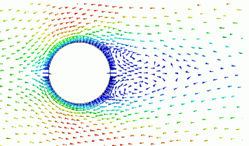
The vectors of the flow velocity distribution around the cylinder are shown below.
The vectors are adjusted to the same length in the graphics setup.
It is known that the so-called twin whirlpools occur behind the cylinder when the Reynolds number is around 30.
Two vortexes appear at the back of the cylinder.

The streamlines are shown below.
The pitch of the startpoints is adjusted in the graphics setup.
The streamlines are generated.

The force on the wall face is shown by the table.
[Column] shows the force which the cylinder receives from the fluid.
Drag F:The force in the flow direction (X-direction) is 6.52 x 10 ^ -9 [N].

The drag coefficient CD can be calculated from the drag F.
Thickness in depth direction t = 1 [mm]
Cross sectional area S = D * t = 0.04 * 0.001 = 4e-5 [m2]
Dynamic pressure Pk = 0.5 * ρ*V^2 = 0.5 * 1.144 * 0.01 * 0.01 = 5.720e-5 [Pa]
Drag coefficient CD = F / Pk / S = 6.52e-9 / 5.720e-5 /4e-5 = 2.85