Home / Examples / Electromagnetic Analysis [Hertz] / Example 27: TDR Analysis
S-parameters obtained in the electromagnetic-harmonic analysis are
converted to a time series of impedance of TDR using Descartes.
Stepped wave is assumed in the TDR analysis.
Unless specified in the list below, the default conditions will be applied.
Results will vary depending on Femtet version and the PC environment.
Item |
Settings |
Analysis Space |
3D |
Model Unit |
mm |
Item |
Settings |
Solver |
Electromagnetic Analysis [Hertz] |
Analysis Type |
Harmonic Analysis |
Tab |
Setting Item |
Settings |
Mesh |
Adaptive Mesh Setting |
General
|
Frequency-Dependent Meshing |
Reference Frequency: 30 x 109 [Hz] Select [The conductor bodies thicker than the skin depth constitute the boundary condition]. |
|
Harmonic Analysis |
Time Domain Setting |
|
Frequency (*2) |
|
|
Sweep Setting |
Select Discrete Sweep (*3) |
*1 The number of iterations is changed to 20 as the adaptive meshing does not converge using the default setting of 5. (Smaller value will shorten calculation time)
*2 Frequency is automatically set based on the time domain setting.
*3 Since the analysis frequency is wide (793 MHz to 50 GHz), discrete sweep is opted so as to avoid worsening analysis accuracy.
To shorten a calculation time, use fast sweep or parallel discrete sweep.
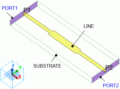
A is a stripline (LINE) is formed inside a substrate (SUBSTRATE).
The stripline has a discontinuous part , and the electromagnetic wave reflects because the characteristic impedance changes here.
Body Number/Type |
Body Attribute Name |
Material Name |
4/Sheet |
LINE |
PEC |
6/Solid |
SUBSTRATE |
DIELECTRIC |
Material Name |
Permittivity |
Conductivity |
DIELECTRIC |
Relative permittivity: 3.9 |
Conductivity Type: Insulator |
PEC |
(Default value) |
Conductivity Type: Perfect conductor |
Boundary Condition Name/Topology |
Tab |
Boundary Condition Type |
Settings |
PORT1/Face |
Electric |
Port |
Integral Path:
Reference Impedance: Select
|
PORT2/Face |
Electric |
Port |
Same as Above. |
Outer Boundary Condition |
Electric |
Electric Wall |
|
In order to convert S-parameters to the time series of impedance of TDR using Descartes,
the reference impedance of all ports must have the same real number.
The impedance over time at PORT1 is displayed instead of S-parameters.
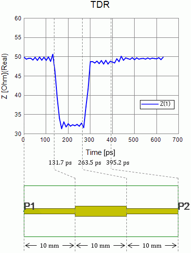
Fig. 1: TDR Analysis Results (Impedance Graph) and Relationship between Time and Substrate's Position
Fig. 1 shows the time series of impedance of TDR obtained from the analysis.
Fig. 1 also shows the relationship between the time and the substrate's position.
There are two ways to examine the results as follows.
The impedance on the line starts from about 50 [Ω] at the time of 0 [s].
This impedance value represents the characteristic impedance (Zpv) of the propagation mode at PORT1.
It can be confirmed in the results table. (See Fig. 2)
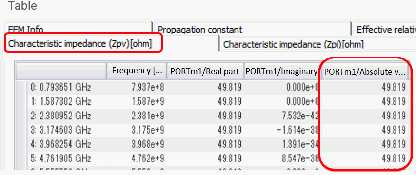
Fig. 2: Results Table (Characteristic Impedance [Zpv])
The impedance changes to about 32 [Ω] at the time of 130 [ps].
This impedance value indicates the characteristic impedance of the line at its discontinuous part.
It can be confirmed by cutting out the discontinuous part from the model and analyzing it.
Fig. 3 is the discontinuous part cut out from the model. Fig. 4 is the analysis results.
PORT3 in Fig. 4 is the port of the discontinuous part. It shows that PORT3's characteristic impedance is about 32 [Ω].
For simplification, the analysis is performed with reference frequency only.
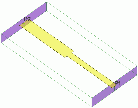
Fig. 3: Model of Discontinuous Part Cut Out From Model
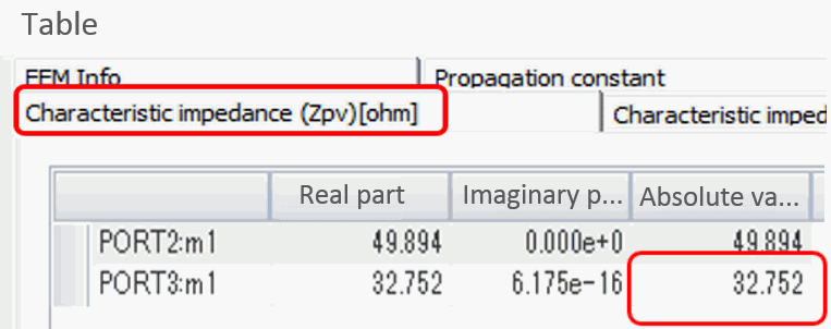
Fig. 4: Results Table for Discontinuous Part (Characteristic Impedance [Zpv])
The time when the impedance changes can be calculated by the position of the discontinuous part on the substrate and the velocity of the electromagnetic waves.
The speed of electromagnetic waves that advance in the stripline v [m/s] can be represented, by using speed of light c0 [m/s] and substrate's relative permittivity εr,
as v = c0 / √εr
Based on the light speed in the vacuum (c0 = 299792458 m/s) and the substrate's relative permittivity (εr = 3.9),
the speed of electromagnetic waves is calculated to be approximately 1.518 × 10⁸ [m/s].
With TDR, impedance of the line is calculated by observing the reflecting waves.
The electromagnetic waves entered from port 1 (PORT1) are reflected in the first discontinuous part at the distance of 10 mm from the port 1.
The reflecting waves will travel a distance of 20mm by the time when they return to the port 1.
It takes about 131.7 ps for the electromagnetic waves with a speed of 1.518 × 10⁸ m/s to travel the distance of 20 mm.
On the TDR graph, you can notice that the impedance changes greatly at around the time of 131.7 ps.
The electromagnetic waves that passed the first discontinuous part are partially reflected at the discontinuous part 20 mm away from the port 1.
The electromagnetic waves reflected here will travel the distance of 40 mm by the time they return to the port 1.
It takes about 263.5 ps for the electromagnetic waves with a speed of 1.518 × 10⁸ m/s to travel the distance of 40 mm.
On the TDR graph, you can notice that the impedance changes greatly at around the time of 263.5 ps.
The electromagnetic waves that passed the second discontinuous part eventually reach the port 2 (PORT2).
If the characteristic impedance of the strip line is not equal to 50 Ω,
then some of the electromagnetic waves will reflect at Port 2 with a reference impedance of 50 Ω.
The electromagnetic waves reflected at the port 2 will travel the distance of 60 mm by the time they return to the port 1.
It takes about 395.2ps for the electromagnetic waves with a speed of 1.518 × 10⁸ m/s to travel the distance of 60 mm.
On the TDR graph, you can notice that the impedance changes also at around the time of 395.2 ps,
and then it is constantly 50 Ω.
To determine the analysis frequency for the harmonic analysis, time is set to 400 ps in the time domain setting.
The graph, however, shows the result up to 630 ps.
It is because Femtet adjusts the number of data when determining the analysis frequency.
Descartes applies Fourier transform to convert S matrix to impedance of TDR.
The number of data that can be handled by Fourier transform is 2n (n is a positive integer).
The rise time of the input signal is 30 ps.
When the time step is one-third of the rise step, it will be 10 ps.
To obtain the result for the time of 400 ps with a 10 ps timestep width, 41 data (time points) are required.
The number of data, 41, is not proper for the Fourier transform.
Set the analysis frequency so that the proper number of 64 (=2 6) is prepared. The results consist of 64 data each having a timestep of 10 ps.
Then the total time of the results is 630 ps.
See also [Time Domain Setting].