General
Home / Examples / Electromagnetic Analysis [Hertz] / Example 25: Loop Antenna
The impedance characteristics of a loop antenna are solved.
Unless specified in the list below, the default conditions will be applied.
Results will vary depending on Femtet version and the PC environment.
Item |
Settings |
Analysis Space |
3D |
Model Unit |
m |
Item |
Settings |
Solver |
Electromagnetic Analysis [Hertz] |
Analysis Type |
Harmonic Analysis |
Harmonic Analysis tab and Open Boundary tab are set as follows.
Tab |
Setting Item |
Settings |
Mesh |
Frequency-Dependent Meshing |
Reference Frequency: 13.56x10⁶ [Hz] Select [The conductor bodies thicker than the skin depth constitute the boundary condition].
As Metal is thicker than the skin depth, boundary condition with copper material loss is applied to the Metal surface. |
Meshing Control |
Tessellations of Periodic Surface Minimum Number of Tessellations: 12 Loop antenna's circular shape is approximated as a polygon. Minimum number of tessellations is 6 by default. That is a hexagon. To increase the accuracy, it is changed to 12. That is a dodecagon. |
|
Harmonic Analysis |
Sweep Type |
Select [Linear Step by Division Number] |
Sweep Setting |
Minimum: 12x106 [Hz] Maximum: 14x106 [Hz] Division: 50 |
|
Sweep Setting |
Select Discrete Sweep |
|
Input |
1.0 [W] |
|
Open Boundary |
Type |
Absorbing Boundary |
Order of Absorbing Boundary |
1st-order |
Fast sweep causes inaccurate results. Here, it is avoided for higher accuracy.
Loop antenna consists of solid bodies. A port and a lumped-constant C are placed between the bodies.
They are sheet bodies set with port and lumped-constant boundary conditions.
The antenna is covered with spherical air, AIR. Its radius is 6 m. 6 m is about a quarter of the wavelength of 13 MHz.
Open boundary is set on the surface of AIR.
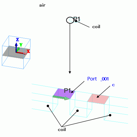
Body Number/Type |
Body Attribute Name |
Material Name |
3/Solid |
coil |
008_Cu (*) |
5/Solid |
coil |
008_Cu (*) |
14/Sheet Body |
Imprinting body |
|
15/Sheet Body |
Imprinting body |
|
16/Solid |
air |
000_Air(*) |
(*) Available from the material DB
Boundary Condition Name/Topology |
Tab |
Boundary Condition Type |
Settings |
Port_001/Face |
Electric |
Port |
Reference Impedance: select Specify enter 50 Ω. Number of Modes: Number of Precalculated Modes: 5 Number of Modes Used in the Actual 3D Analysis: 1 Select Modes: None |
C/Face |
Electric |
Lumped Constant |
Capacitance: 20.65x10⁻¹² [F] |
Outer Boundary Condition |
Electric |
Open Boundary |
Select on the open boundary tab of the analysis condition setting. |
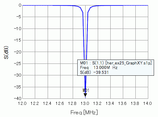
Shown below are the results. The left diagram is the frequency response of the impedance. The center is 50 ohms. The right diagram is the frequency response of S11 [dB].

S11 [dB] is large in the graph, which means that the reflected power is large. By changing the port's reference impedance, the reflection can be reduced.
Impedance at 13GHz is 2.348-j10.158 [Ω] in the Smith chart above. To minimize the reflected power, set the port’s reference impedance to the conjugate value (2.348+j10.158 [Ω]).
The results with this setting are shown below. As the impedance at 13MHz is used as a reference impedance, the matching at 13MHz can be seen.
The reflection is reduced.
To obtain the same results as shown here, be aware that the same meshes must be used before and after changing the reference impedance.
It must be noted if the reference impedance is changed, meshes created by adaptive meshing will also be changed.
The impedance of the antenna may change, and proper matching cannot be achieved. To avoid it, you may treat each project separately before and after changing the reference impedance,
and select [Run Solver with Existing Meshes], and utilize meshes prepared in advance. You need to specify the pdt file created before changing the reference impedance.
See [[Simple Mode] Calculation of Electromagnetic Waves Directivity] or [[Detailed Mode] Calculation of Electromagnetic Waves Directivity] for display of radiation patterns