
General
Home / Examples / Acoustic Analysis [Mach] / Example 13 Sound-absorbing Material
The model of this example is created referring to the website of Architectural Institute of Japan (AIJ).
The characteristics of a sound-absorbing material is analyzed with the Miki model *1,*2.
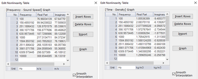
The material properties of the sound-absorbing material are input by the frequency response table of complex sound velocity and complex density.
The resultant material properties of the sound-absorbing material are compared with measurements obtained from AIJ.
Results will vary depending on Femtet version and the PC environment.
Item |
Settings |
Analysis Space |
2D Thickness in Depth Direction: 1 [mm] |
Model Unit |
mm |
Item |
Settings |
Solver |
Acoustic Analysis [Mach] |
Analysis Type |
Harmonic Analysis |
Mesh tab and Harmonic Analysis tab are set as follows.
Tab |
Setting Item |
Settings |
Mesh |
General Mesh Size: |
1 |
Harmonic Analysis |
Frequency |
Minimum: 100 [Hz] Maximum: 10000 [Hz] |
Interval |
Select [Log Step] Division: 100 |
|
Frequency Sweep |
Select Discrete Sweep. |
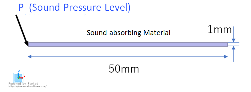
Create a rectangular sheet body, 50 x 1 [mm], and set sound-absorbing material to the body.
Set the pressure level boundary condition, P, to the edge at the left end of the body. Three other edges are without boundary conditions, leading to the external boundary condition of the rigid wall.
Body Number/Type |
Body Attribute Name |
Material Name |
0/Solid |
Sound-absorbing Material |
Sound-absorbing Material |
How to determine the material properties is crucial in this example. Calculate the complex sound speed and complex density of the material in Excel and enter them in the table below. The calculation procedures are shown below.
Using the Miki model, which is popular for the internal fluid model of porous material, the frequency responses of the characteristic acoustic impedance, Zf, and complex wavenumber, kf, are given by equations (1) to (3).
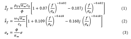
Material properties below are used.
Airflow Resistivity (σ): 6900 [N/m4]
Tortuosity (α∞): 1.0 [ ]
Porosity(φ): 1.0 [ ]
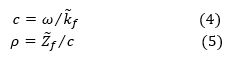
Complex sound speed, c, and complex density, ρ, are required for the acoustic analysis in Femtet. They are obtained from equations (4) and (5) using complex wavenumber and characteristic acoustic impedance resulted from the Miki model.
Boundary Condition Name/Topology |
Tab |
Boundary Condition Type |
Settings |
P/Edge |
Sound Wave |
Sound Pressure Level |
10dB |
Outer Boundary Condition |
Acoustic |
Rigid Wall |
|
The normalized impedance and the frequency response of the sound-absorbing material are compared with theoretical values and measurements. At first, the radiation impedance in the result table in Femtet is shown, and then how to calculate the normalized impedance and absorption ratio in Excel, and the calculation results are shown.
1. Frequency Response of Radiation Impedance
In the Table of results, go to the Radiation Impedance tab, select [Show all results summary], and click the [Graph] button. The frequency response graph will appear.
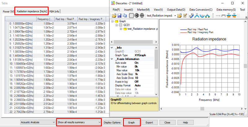
Fig. 1 Frequency Response of Radiation Impedance (Table and Graph)
2. Frequency Response of Normalized Impedance
Normalized Impedance, Zn, is obtained by normalizing with the characteristic acoustic impedance of air.
Calculate it in Excel to compare with theoretical values and measurements. Femtet alone is not sufficient to achieve the intended results. Therefore, Excel is used.
After the radiation impedance is solved in Femtet, they are input in Excel, where Zn is calculated with Equations (6) and (7).
Zr can be input into Excel from the result table by using copy and paste commands or importing a csv file. Then it is converted to acoustic impedance per unit area.
Z = Zr/S (6)
S is an area of the driving portion. (S=0.001*0.001=1.0e-6 [m2])
Then Zn is obtained by normalizing with Zo.
Zn = Z/Z0 (7)
where Z0 = (density of air) x (sound velocity of air).
Fig. 2 shows an overlaid graph of Zn values obtained in Excel, theoretical values, and measurements. The calculated results match very well with theoretical values and measurements, except for values near 100 [Hz].
3. Frequency Response of Absorption Ratio
The absorption ratio is obtained. At first, the reflection coefficient is given by Equation (8) and then the absorption ratio is given by Equation (9).
r = (Z-Z0)/(Z+Z0) (8)
Absorption Ratio = 1-|r|^2 (9)
Fig. 3 shows the frequency response of the absorption ratio.
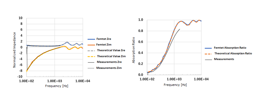
Fig. 2 Frequency Response of Normalized Impedance Fig.3 Frequency Response of Absorption Ratio
Zre and Zim are the real and imaginary parts of the impedance, respectively.
Reference:
*1 Miki Y., Acoustical properties of porous materials - Modifications of Delany-Bazley models, J. Acoust. Soc. Jpn (E). 11(1), 1990, pp. 19-24
*2 Miki Y., Acoustical properties of porous materials - Generalization of empirical models, J. Acoust. Soc. Jpn (E). 11(1), 1990, pp. 25-28