General
Home / Examples / Coupled Analysis / Piezoelectric-Acoustic Analysis [Rayleigh/Mach] / Example 2: Fully Coupled Analysis
Fully-coupled analysis is performed for the example 1: Harmonic Analysis.
Results will vary depending on Femtet version and the PC environment.
Item |
Settings |
Analysis Space |
3D |
Model Unit |
m |
The solvers are Rayleigh and Mach.
Item |
Settings |
Solver |
Piezoelectric Analysis [Rayleigh] Acoustic Analysis [Mach] |
Analysis Type |
Harmonic Analysis |
Options |
Select [Fully-coupled Analysis] |
The harmonics analysis tab is set up as follows.
The sound waves propagate outside the analysis region. Therefore the open boundary condition below is applied initially.
The default conditions will be applied.
Tabs |
Setting Item |
Settings |
Harmonic Analysis |
Frequency |
Minimum: 1500 [Hz] Maximum: 1700 [Hz] |
Sweep Type: Linear Step by Division Number |
Division: 10 |
|
Open Boundary Tab |
Type |
Absorbing Boundary |
Order of Absorbing Boundary |
1st-order |
|
Coordinates of Origin |
x = y = z = 0 |
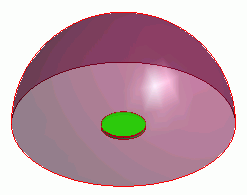
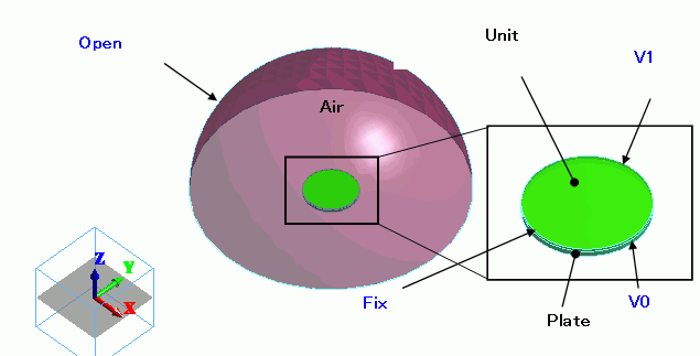
A piezoelectric disc (Unit) is placed on an aluminum disc (Plate). The hemispheric body (Air) covers the upper area.
Body Number/Type |
Body Attribute Name |
Material Name |
0/Solid |
Air |
000_Air(*) |
1/Solid |
Unit |
000_P-4 * |
2/Solid |
Plate |
001_Al * |
* Available from the material DB
Unit and Plate are for the piezoelectric analysis only, whereas Air is for the acoustic analysis only.
Body Attribute Name |
Analysis Domain (Solver) |
Unit |
Piezoelectric Analysis (Rayleigh) |
Plate |
Piezoelectric Analysis (Rayleigh) |
Air |
Acoustic Analysis (Mach) |
Cautions:
In this analysis, it is necessary to specify the analysis domain.
That is to specify either piezoelectric analysis or acoustic analysis on the analysis domain tab.
The side periphery of the model is fixed in the Z direction.
Electric wall is set on the top and bottom faces of the piezoelectric disc.
The open boundary is set on the hemispheric surface.
Boundary Condition Name/Topology |
Tab |
Boundary Condition Type |
Settings |
V0/Face |
Electric |
Electric Wall |
Electric Potential Specified: Electric Potential 0 [V] |
V1/Face |
Electric |
Electric Wall |
Electric Potential Specified: Electric Potential 10 [V] |
Fix/Face |
Mechanical |
Displacement |
Select UZ and set UZ=0 |
Open |
Acoustic |
Open Boundary |
|
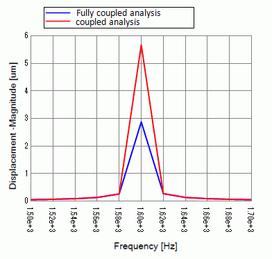
The displacement of the piezoelectric disc is examined.
Horizontal axis: Frequency, Vertical axis: Displacement Z component. The displacement is measured at the center (0, 0, 0) of the disc where the magnitude of displacement is the largest.
Under the fully coupled condition, the air can suppress the vibration of the disc, so the displacement magnitude is smaller at the resonant frequency of 1.6 [kHz]. When moving away from the resonant frequency, the difference in magnitude becomes very small.