Home / Examples / Piezoelectric Analysis [Rayleigh] / Example 18: Effect of Tensile Force
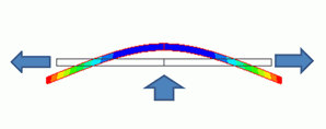
The effect of tensile force is studied. As in the figure above, a bar is pulled at both ends and pushed upward from the bottom at the same time. If the pulling force becomes large, deformation due to the pushing force will be small.
Although the material used in this exercise has no piezoelectricity, the analysis is applicable to the piezoelectric material.
By utilizing symmetry, a half model is analyzed.
Results will vary depending on Femtet version and the PC environment.
Item |
Settings |
Analysis Space |
2D |
Model Unit |
mm |
Item |
Settings |
Solver |
Piezoelectric Analysis [Rayleigh] |
Analysis Type |
Static Analysis |
Analysis Plane |
2D Section |
Large Deformation |
Select [Large Displacement]. |
Variables to Constrain |
Select electric potential X Displacement: Deselect Y Displacement: Select Z Displacement: Deselect |
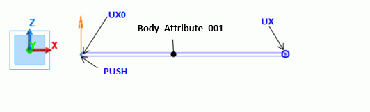
By utilizing symmetry, a half model is analyzed. The symmetric boundary condition (UX0) is set to the left end.
The displacement vector (boundary condition UX) is set to the right end since it is pulled in the right direction. The lumped load boundary condition (PUSH) is set to the tip on the bottom of the left end.
Body Number/Type |
Body Attribute Name |
Material Name |
0/Sheet Body |
Body_Attribute_001 |
Material_Property_001 |
Material Name |
Tab |
|
Material_Property_001 |
Piezoelectricity |
Piezoelectricity: No Anisotropy: Isotropic Young's Modulus= 2x10¹¹ [Pa] Poisson's ratio= 0.3 |
Boundary Condition Name/Topology |
Tab |
Boundary Condition Type |
Setting |
PUSH/Vertex |
Mechanical |
Lumped Vertex Load |
X=Y=0.0 [N] Z=1.0 [N]
|
UX/Vertex |
Mechanical |
Displacement |
Select all UX/UY/UZ components.
X=0.1 [mm] Y=Z=0.0 [mm]
|
UX0/Edge |
Symmetry/Continuity |
|
Symmetry * |
* X direction is fixed while Z direction is not fixed.
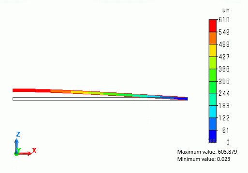
The right end with the boundary condition UX is displaced by 0.1 mm in the X direction. The left end is pushed upward. The obtained results are as expected.
To examine the effect of tensile force, X displacement of the boundary condition UX is changed from the current 0.1 mm to 0.0 mm and 0.05 mm.
Also, the large displacement is deselected on the piezoelectric analysis tab and the analysis was executed. The results are shown as below.
[Large Displacement ON] and [Large Displacement OFF] represent the results with and without large displacement option respectively.
With [Large Displacement]] deselected, the analysis is linear. The effect of the boundary condition UX is not found.
With [Large Displacement] selected, the analysis is nonlinear. The Z deformation is gradually diminished as the tensile force becomes larger.

The dot indicated by a red arrow represents the setting status of the project file of this example. It also corresponds to the contour diagram above.