CAE Software【Femtet】Murata Software Co., Ltd.
Example6 Flow Path with Multiple Inlets and Outlets
 General
-
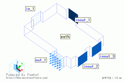
A flow path with multiple inlets and outlets is solved.
-
Forced inflow and forced outflow are set one each.
Natural inflow/outflow is set to the three areas where it is not known if the flow is incoming or outgoing. -
Unless specified in the list below, the default conditions are applied.
Analysis Space
|
Item |
Setting |
|
Analysis Space |
3D |
|
Model Unit |
mm |
Analysis Conditions
|
Item |
Tab |
Setting |
|
Solver |
Solver selection |
Fluid analysis [Bernoulli] |
|
Analysis Type |
Fluid analysis |
Steady-state analysis |
|
Meshing Setup |
Mesh |
General mesh size: 5[mm] |
Model

Body Attributes and Materials
|
Body Number/Type |
Body Attribute Name |
Material Name |
|
6/Solid |
Path |
100_Water * |
* Available from the material DB
Boundary Condition
|
Boundary Condition Name/Topology |
Tab |
Boundary Condition Type |
Setting |
|
in_1/Face |
Fluid |
Inlet |
Forced inflow Specify flow velocity: 0.1[m/s] |
|
out_1/Face |
Fluid |
Outlet |
Forced outflow |
|
inout_1/Face |
Fluid |
Inlet/Outlet |
Natural Inflow/Outflow |
|
inout_2/Face |
Fluid |
Inlet/Outlet |
Natural Inflow/Outflow |
|
inout_3/Face |
Fluid |
Inlet/Outlet |
Natural Inflow/Outflow |
Results
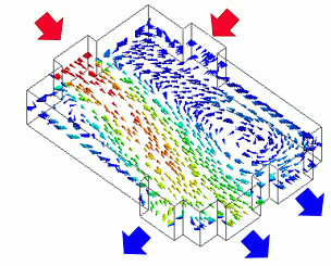
The vectors of the flow velocity are shown below.
The vectors are adjusted to the same length in the graphics setup.
For the three areas where it was not know if they were inflow or outflow before the analysis,
the result shows that inout_1 is inflow, inout_2 and inout_3 are outflow.

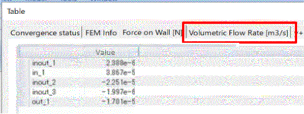
The table of the volumetric flow rate is shown as follows.
The inflow rate is shown in the positive value and the outflow rate in the negative values.
For the inflow rate, inout_1 and in_1 are added totaling 4.11e-5[m3/s].
For the outflow rate, inout_2, inout_3, and out_1 are added totaling 4.15e-5[m3/2].
The inflow face and the outflow rate are almost balanced.