
CAE Software【Femtet】Murata Software Co., Ltd.

Example7 Transient Analysis of Flow around Still Fan
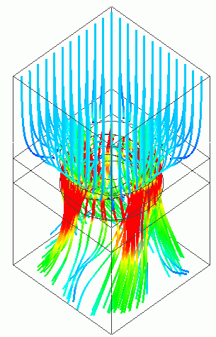
General
-
The flow around a still fan is analyzed.
-
The wind flowing in to the still fan is analyzed and the pressure on the fan is solved.
-
The fan does not rotate. The rotation of the fan is not taken into account.
-
Unless specified in the list below, the default conditions will be applied.
Analysis Space
|
Item |
Setting |
|
Analysis Space |
3D |
|
Model Unit |
m |
Analysis Condition
|
Item |
Tab |
Setting |
||||||||
|
Solver |
Solver Selection |
Fluid analysis [Bernoulli] |
||||||||
|
Analysis Type |
Fluid Analysis |
Transient analysis |
||||||||
|
Timestep |
Transient analysis |
Timestep: Specify
|
||||||||
|
Meshing Setup |
Mesh |
General mesh size: 0.2[m] Fan: 0.05[m] Case 0.08[m] |
Model
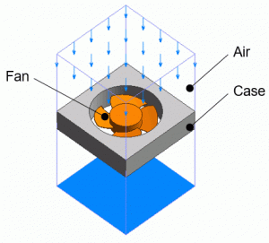
A casing and a fan are placed in the box of air. The wind is blowing in from the inflow boundary at the top of the air domain.

Body Attributes and Materials
|
Body Number/Type |
Body Attribute Name |
Material Name |
|
24/Solid |
Case |
001_Al * |
|
25/Solid |
Fan |
104_Stainless_steel * |
|
26/Solid |
Air |
000_Air * |
* Available from the material DB
Boundary Condition
|
Boundary Condition Name/Topology |
Tab |
Boundary Condition Type |
Setting |
|
In/Face |
Fluid |
Inlet |
Specify flow velocity: 2[m/s] |
|
Out/Face |
Fluid |
Outlet |
Natural outflow |
Results
Shown below is a vector diagram of flow velocity (XYZ and XY vectors) at the last timestep (1[s]).
Before reaching the fan, the air flow has Z component only. The fan generates the flow velocity on the XY plane.
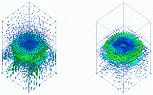
 Fig. 1: Vectors of Flow Velocity (left: XYZ vectors right: XY vectors)
Fig. 2 shows the streamlines at the last timestep. The streamlines indicate that the air flow is accelerated due to the fan.
For easy viewing of the accelerated flow, the maximum value is set to 10[m/s] and the distribution interval of startpoints to 0.1m.

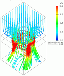
Fig. 2: Streamlines at the Last Timestep
Lastly, the pressure (static pressure) applied to the fan at the last timestep is shown in Fig. 3. The pressure at the tips of the blades is low.
This means that the air flow is most accelerated at the blade tips, reducing the static pressure.
-
Example 70 of Stress Analysis is conducted using this pressure.

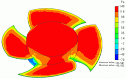
Fig. 3: Pressure Applied to the Still Fan

