CAE Software【Femtet】Murata Software Co., Ltd.

Example2 Capacitance Change by Thermal Expansion

General
-
Capacitance change of a capacitor by thermal expansion is analyzed.
-
[Analysis with deformed shape taken into consideration] is used.
-
Unless specified in the list below, the default conditions will be applied.
Three analysis models are prepared.
・Before deformation (electric field analysis)
・Deformed shape (mechanical stress analysis)
・After deformation (electric field analysis)
See [Analysis with the Deformed Shape Taken into Account] for more information.
Analysis Model 1: Before Deformation
Set up analysis before the deformation. The model is named [Before deformation].
Analysis Space
|
Item |
Setting |
|
Analysis Space |
3D |
|
Model unit |
mm |
Analysis Condition
|
Item |
Setting |
|
Solver |
Electric field analysis [Coulomb] |
|
Analysis Type |
Static analysis (capacitance) |
|
Options |
None |
In actuality, the electric field exists outside the analysis domain. Therefore the open boundary condition below is applied initially.
|
Tab |
Setting Item |
Setting |
|
Open Boundary Tab |
Type |
Absorbing boundary |
|
Order of Absorbing Boundary |
1st degree |
Graphical Object
Create a cubic solid body for a dielectric (Block).
Create the voltage-setting places by the sheet bodies to set the voltage boundary condition on the top and bottom faces of the dielectric.
Body Attributes and Materials
|
Body Number/Type |
Body Attribute Name |
Material Name |
|
0/Solid |
Block |
001_Alumina * |
|
1/Sheet |
None (imprinting body) |
|
|
2/Sheet |
None (imprinting body) |
|
* Available from the material DB
Boundary Condition
|
Boundary Condition Name/Topology |
Tab |
Boundary Condition Type |
Setting |
|
V0/Face |
Electric |
Electric wall |
Voltage specified, 1[V] |
|
V1/Face |
Electric |
Electric wall |
Voltage specified, 0[V] |
|
Outer Boundary Condition * |
Electric |
Open Boundary |
Set up on the open boundary tab. |
To set Outer Boundary Condition, go to the [Model] tab
and click [Outer Boundary Condition] .
Analysis Model 2: Deformed Shape Calculation
Set the mechanical stress analysis to calculate the deformation caused by the thermal expansion.
Copy Analysis Model 1 (before deformation) and set up as follows. The model is named [Deformed shape calculation].
See [Copy Analysis Model into Project] for the details.
Analysis Condition
|
Item |
Setting |
|
Solver |
Mechanical stress analysis [Galileo] |
|
Analysis Type |
Static Analysis |
|
Options |
Thermal Load |
|
Tab |
Setting Item |
Setting |
|
Step/Thermal Load |
Step Setting |
Thermal load analysis |
|
Reference temperature |
25[deg] |
|
|
Reached Temperature |
200[deg] |
Analysis Model 3: After Deformation
Set up the analysis that takes the deformed shape into account.
Copy Analysis Model 1 (before deformation) and set up as follows. The model is named [After deformation].
See [Copy Analysis Model into Project] for the details.
Analysis Condition
Specify Analysis Model 2 (Deformation shape calculation) on the result import tab.
|
Tab |
Setting Item |
Setting |
|
Result Import |
Import Type |
Deformed shape |
|
Specify Results |
Specify Analysis Model [Deformed Shape Calculation] |
Run Mesher/Solver
Run the solver with all analysis models. Calculation of Analysis Model 2 (deformed shape) must be completed before going on to Analysis Model 3 (after deformation).
Results
To see the calculation results, go to the [Results] tab
and click [Table] .
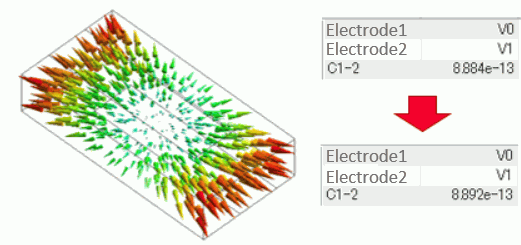
Results of Analysis Model 1 (before deformation) are as follows.
The capacitance of C1-2 is 0.884[pF].
A displacement diagram of Analysis Model 2 (deformed shape calculation) is shown as below.
The expansion due to the temperature change is observed.
Results of Analysis Model 3 (After deformation) are as follows.
The capacitance of C1-2 is 0.892[pF]. It confirms that the capacitance is increased due to the deformation.

