CAE Software【Femtet】Murata Software Co., Ltd.

Example20 Two Plates Adhered at One End (Simple Contact #2)

General
-
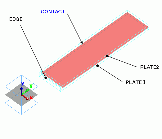
This is similar to Exercise 19, but the material of both plates is the same. They are adhered only at one end instead of both ends.
The simple contact boundary condition is set on the inner faces of the plates. The deformation caused by thermal load is solved. -
The deformation, the displacement and the mechanical stress are solved.
-
Unless specified in the list below, the default conditions will be applied.
Analysis Space
|
Item |
Settings |
|
Analysis Space |
3D |
|
Model unit |
mm |
Analysis Conditions
The temperature is applied evenly on the model.
Opt for the thermal load in the analysis condition, and set the reference temperature and the reached temperature.
There is no need to couple with the thermal analysis [Watt].
|
Item |
Settings |
|
Solvers |
Mechanical Stress Analysis [Galileo] |
|
Analysis Type |
Static analysis |
|
Options |
Select “Thermal load”. |
The Step/Thermal Load tab is set as follows.
Analysis is performed with the reached temperature of 0 deg.
|
Tab |
Setting Item |
Settings |
|
Step/Thermal Load |
Reference temperature |
25[deg] |
|
Step/Reached Temperature Setting |
Step 1: 0[deg] |
Model
Two plates, PLATE1 and PLATE2, have the same coefficient of expansion, while that is doubled for the joint material, EDGE.

Body Attributes and Materials
|
Body Number/Type |
Body Attribute Name |
Material Name |
|
0/Solid |
TERMINAL |
MAT2 |
|
1/Solid |
PLATE1 |
MAT1 |
|
2/Solid |
PLATE2 |
MAT1 |
The material properties are set up as follows:
MAT2 has very different coefficient of (thermal) expansion from MAT1.
|
Material Name |
Tab |
Properties |
|
MAT1 |
Elasticity |
Young’s modulus: 10×10^9[Pa] Poisson’s ratio: 0.3 |
|
Coefficient of Expansion |
5×10^-6[1/deg] |
|
|
MAT2 |
Elasticity |
Young’s modulus: 10×10^9[Pa] Poisson’s ratio: 0.3 |
|
Coefficient of Expansion |
10×10^-6[1/deg] |
Boundary Conditions
|
Boundary Condition Name/Topology |
Tab |
Boundary Condition Type |
Settings |
|
CONTACT/Face |
Mechanical |
Simple contact |
Simple Contact Classification : Automatic Judgment |
Results
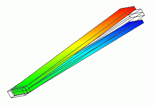
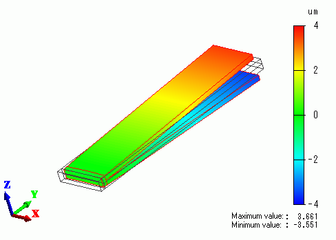
The Z-direction displacement is shown below by contour. The contour are the Z displacement.

At lower temperature, the joint material shrinks more than the plates. As a result, the other ends of the plates open.
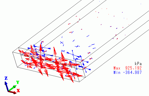
The vectors of mechanical stress around EDGE are shown below.

EDGE is getting the tensile stress, whereas the plates are getting the compression stress.

