
CAE Software【Femtet】Murata Software Co., Ltd.

Example21 Plastic Block Set with Uniform Displacement
General
-
The “uniform displacement” boundary condition is studied.
-
The displacement is constant for each topology given the uniform displacement boundary condition. There will be no deformation.
-
The uniform displacement can be set for each direction.
-
The deformation, the displacement and the mechanical stress are solved.
-
Unless specified in the list below, the default conditions will be applied.
Analysis Space
|
Item |
Settings |
|
Analysis Space |
3D |
|
Model unit |
mm |
Analysis Conditions
Uniform displacement is specified in the boundary condition of the model.
|
Item |
Settings |
|
Solver |
Mechanical Stress Analysis [Galileo] |
|
Analysis Type |
Static analysis |
|
Options |
Select Thermal load. |
The Step/Thermal Load tab is set as follows.
|
Tabs |
Setting Item |
Settings |
|
Step/Thermal Load |
Reference temperature |
25[deg] |
|
Step/Reached Temperature Setting |
Step 1: 85[deg] |
Model
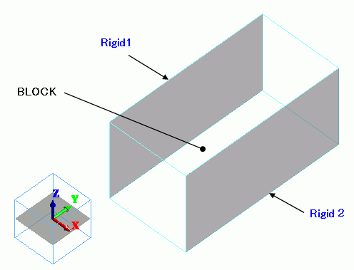
The box-shape solid body is created. The material is the polyethylene.
Two faces are set with the uniform displacement boundary condition.
The boundary conditions are called RIGID1 and RIGID2.
Body Attributes and Materials
|
Body Number/Type |
Body Attribute Name |
Material Name |
|
0/Solid |
BLOCK |
000_Polyethylene(PE) * |
* Available from the Material DB
Boundary Conditions
|
Boundary Condition Name/Topology |
Tab |
Boundary Condition Type |
Settings |
|
Rigid1/Face |
Mechanical |
Free |
Uniform displacement: Select UX: Select UY: Select UZ: Select |
|
Rigid2/Face |
Mechanical |
Free |
Uniform displacement: Select UX: Select UY: Select UZ: Select |
Results
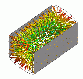
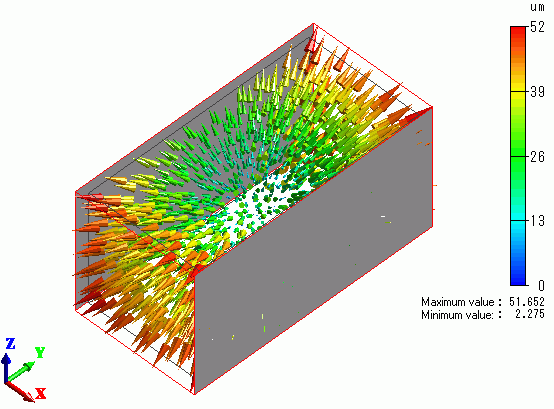
The vectors of the deformation are shown below.
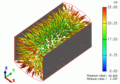
The model swells due to the temperature increase. The faces set with uniform displacement displace in the X direction but exhibit no deformation.
Two uniform displacement faces are given different names on the model above. If they have the same name, the results will look like below.
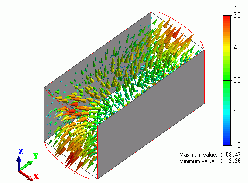
The displacements of both faces need to be exactly the same. Since each face’s direction of displacement is opposite,
the displacement is canceled.
Uniform displacement can be set for each direction.
Deselect UY and UZ. The result will be like below.
The displacement is fixed in X direction, but free in Y and Z directions.

