CAE Software【Femtet】Murata Software Co., Ltd.

Example34 Energy Release Rate

General
-
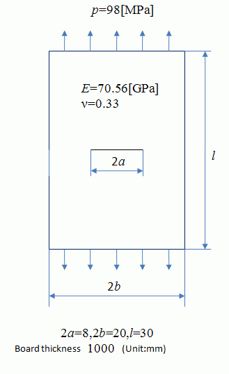
A plate with a crack is expanded and the mechanical stresses are analyzed.
-
From the resulting strain energy, the energy release rate and the stress intensity factor are calculated.
-
See Exercise 46: Energy Release Rate Calculated by J Integral for another way to solve it.
-
Unless specified in the list below, the default conditions will be applied.
Analysis Space
|
Item |
Settings |
|
Analysis Space |
2D |
|
Model unit |
mm |
Analysis Conditions
|
Item |
Settings |
|
Solver |
Mechanical Stress Analysis [Galileo] |
|
Analysis Type |
Static analysis |
|
Options |
N/A |
Model
A plate with a crack is expanded and the mechanical stresses are analyzed.
The tensile strength can be evaluated by the stress intensity factor, K.
The theoretical value of K is given by the equation below.
We acquire K through the simulation and compare it with the theoretical value.


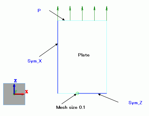
The model is symmetric vertically and horizontally. Therefore a quarter of the model is analyzed.
Select [Reflective] on the Symmetry/Continuity tab for each face of symmetry.

Body Attributes and Materials
|
Body Number/Type |
Body Attribute Name |
Material Name |
|
0/Sheet |
Plate |
Fe |
The thickness of sheet body is set to 1[m].
|
Body Attribute Name |
Tab |
Settings |
|
Plate |
Thickness/Width |
Thickness of Sheet Body: 1000 |
Set Young’s modulus and Poisson’s ratio.
|
Material Name |
Young’s modulus |
Poisson’s ratio. |
|
PlateMat* |
70.56×10^9[Pa] |
0.33 |
*Depends on the material.
Boundary Conditions
|
Boundary Condition Name/Topology |
Tab |
Boundary Condition Type |
Settings |
|
Sym_X/Edge |
Symmetry/Continuity |
Symmetry |
Reflective |
|
Sym_Z/Edge |
Mechanical |
Symmetry |
Reflective |
|
P/Edge |
Mechanical |
Pressure |
-98×10^6[Pa] |
Results
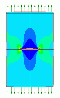
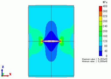
In the figure below, the maximum principal stress is superposed on displacement diagram.
The color scale range is 0 to 400MPa.
The full model can be viewed.
High stress is exhibited at the end of the crack.

Energy Release Rate
It is not practical to directly relate the stress to the ultimate tensile strength,
since the stress depends on the meshing.
It is common to use the energy release rate and the stress intensity factor to estimate the ultimate tensile strength.
The energy release rate (g) is given by the following equation in terms of the strain energy (U) and the length (a).
 (1)
(1)
Here, the length changes from a=4.05 to a=3.95.
With this quarter model, U=12.1805977[J] at a=4.05[mm] and
U=12.0728236 at a=3.95. So for the full model,
 (2)
(2)
Note that it is multiplied by 4 as the full model’s energy is 4 times as much as the quarter model’s energy.
Also note that it is divided by 2 as the full model’s crack is twice as long as the quarter model’s crack.
Stress Intensity Factor
In case of 2D, the energy release rate, g and the stress intensity factor, K have the following relationship.
Planar stress
 (3)
(3)
Planar strain
 (4)
(4)
Equation (3) is applicable for this exercise. By using Equation (2), we get the following.
 (5)
(5)
This value matches quite well with the theoretical value.

