CAE Software【Femtet】Murata Software Co., Ltd.

Example53 Both Ends Supported Bar under Distributed Load
General
-
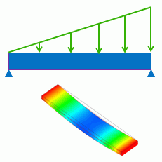
Distributed load is applied on a both ends supported bar.
-
The top face is set with the distributed load boundary condition. See [How to Set Distributed Boundary Condition and Body Attribute] for more information.
-
The deformation, the displacement and the mechanical stress are solved.
-
Unless specified in the list below, the default conditions will be applied.
Analysis Space
|
Item |
Settings |
|
Analysis Space |
3D |
|
Model unit |
mm |
Analysis Conditions
The default conditions are good enough for this exercise.
|
Item |
Settings |
|
Solver |
Mechanical Stress Analysis [Galileo] |
|
Analysis Type |
Static analysis |
|
Options |
N/A |
Model
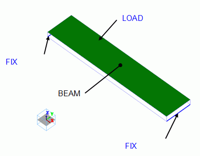
The bar is a rectangular solid body. The material is polycarbonate.
Distributed load is applied on the top face. Both edges of the bottom face is fixed in Z direction.
Body Attributes and Materials
|
Body Number/Type |
Body Attribute Name |
Material Name |
|
0/Solid |
BEAM |
002_Polycarbonate(PC) * |
* Available from the Material DB
Boundary Conditions
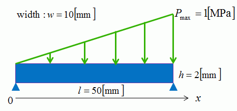
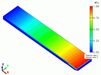
Tapered pressure is applied as shown below.
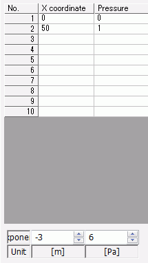
Pressure = 0 at X = 0, Pressure = 1 [MPa] at X = 50 [mm]
|
Boundary Condition Name/Topology |
Tab |
Boundary Condition Type |
Settings |
|
FIX/Face |
Mechanical |
Displacement |
Select the Z component. |
|
LOAD/Face |
Mechanical |
Pressure |
Select “Use distribution data”.
[Coordinates-Pressure] Table
|
How to view the distribution
Click “Run Mesher” on the pull-down menu of [Run Mesher/Solver] and see the meshing result.
Select “Distributed pressure” at [Field] to view the entered distribution.
You may click “Run Mesher/Solver” instead. In that case, select “Mesh Information” at [Mode] and then select “Distributed pressure” at [Field].
The linearly changing pressure can be observed.
Results
The figure below is the gradation contour of Z component of Displacement.
It is a bottom view.
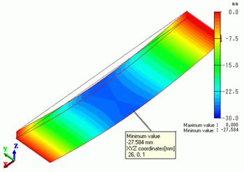
The lowest displacement is 27.584 [mm] at X = 26 [mm]
The formula

gives 27.297 [mm] at X = 25.967 [mm]
They are well matched.
Here,
y: Displacement, l, w, h: Dimensions of the bar, Pmax: Maximum pressure, x: Coordinate, E: Young’s modulus, I: Second moment of area
Second moment of area for a rectangle section is given by

The contour indicates the X normal stress.
It is a bottom view.
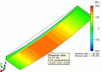
The maximum stress is 241.087 [MPa] at X = 28.938 [mm]
The formula

gives 240.563 [MPa] at X = 28.867 [mm]
They are well matched.
Here,
σ: Stress, l, w, h: Dimensions of the bar, Pmax: Maximum pressure, x: Coordinate, Z: Section modulus
Section modulus for a rectangle section is given by


