CAE Software【Femtet】Murata Software Co., Ltd.

Example62 Plane Stress of Multilayer Sheet

General
-
An analysis model consists of sheet bodies, on which copper, nickel, and gold are plated respectively. A thermal load analysis is performed.
-
The deformation, the displacement distribution, and the strain energy distribution on each plate are solved.
-
Unless specified in the list below, the default conditions will be applied.
Analysis Condition
The temperature is applied evenly on the model.
Select Thermal load and set the reference temperature and the reached temperature.
|
Item |
Setting |
|
Solver |
Stress analysis [Galileo] |
|
Analysis Space |
3D |
|
Analysis Type |
Static analysis |
|
Unit |
mm |
|
Options |
Select Thermal load. |
The Step/Thermal Load tab is set as follows.
|
Tab |
Setting Item |
Setting |
|
Step/Thermal Load |
Reference temperature |
25[deg] |
|
Reached temperature |
120[deg] |
Model
An alumina substrate is created by a box. A sheet body is created on the upper face of the box. Copy the sheet twice making it three.
Each sheet is given copper, nickel, and gold as material property. They are also given thickness as body attribute.
The sample project contains a model whose electrodes are made of solid bodies in addition to the one with electrodes of sheet bodies for comparison purpose.
Body Attributes and Materials
Multilayer Sheet Model
|
Body Number/Type |
Body Attribute Name |
Thickness of Sheet Body |
Material Name |
|
0/Solid |
Substrate |
|
001_Alumina * |
|
4/Sheet |
Electrode1 |
20×10-3[mm] |
008_Cu (*) |
|
5/Sheet |
Electrode2 |
5×10⁻³[mm] |
010_Ni * |
|
6/Sheet |
Electrode2 |
5×10⁻³[mm] |
002_Au * |
* Available from the material DB
Multilayer Solid Model (Thickness is same as that of sheet body)
|
Body Number/Type |
Body Attribute Name |
Material Name |
|
0/Solid |
Substrate |
001_Alumina * |
|
4/Solid |
Electrode1 |
008_Cu (*) |
|
5/Solid |
Electrode2 |
010_Ni * |
|
6/Solid |
Electrode2 |
002_Au * |
* Available from the material DB
Boundary Condition
None
Results
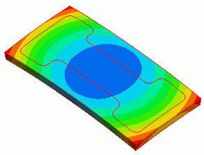
The displacement diagram is shown below. The contour diagram shows the magnitude of displacement. The unit is [um].
Due to the expansion of the electrodes, a convex warpage is observed.
The multilayer sheet model and the multilayer solid model show almost the same displacement.
The same mesh size is given to the models. The number of elements of the multilayer sheet model is 24640, and the multilayer solid model is 54576.
The calculation load is greatly reduced for the multilayer sheet model.
Below are the result tables of the strain energy for each body.
The multilayer sheet model and the multilayer solid model show almost the same results.
Of the three electrode sheets, the strain energy is most stored in the Electrode 1 (Cu).
Below are the contour diagrams of strain energy density at each electrode layer.
The results of the multilayer sheet model is as follows.
The results of the solid model is as follows.
The multilayer sheet model and the multilayer solid model show almost the same strain energy density.
The strain energy is different even if the displacement is same. It is because each electrode layer has different elasticity, coefficient of expansion, and thickness.
As the sheet bodies of the model are overlapping, the contour display of each sheet will overlap if they are output at the same time.
Select the body only of your interest on the body tree to see the results.
(Note)
If multiple sheet bodies are created on the surface of a solid body, they will work as multilayer planar stress sheet.
The stiffness in the face direction can be analyzed with the multilayer sheet model in the same way as the multilayer solid model. The flexural stiffness, however, is ignored.
The laminated shell structure with the flexural stiffness taken into account is not supported. To take the flexural stiffness into account, use solid body.
To use Mesher G1, the multilayer sheet body must be the same form. (The body form is irrelevant in the case of Mesher G2.)

