
CAE Software【Femtet】Murata Software Co., Ltd.
Example64 Elastic Collision with Initial Velocity Distribution
General
-
An object is given an initial velocity, and collides with a rotating object. Transient analysis is performed on the elastic collision.
-
The stress distribution, the displacement distribution, and the velocity distribution during the collision are solved.
-
Unless specified in the list below, the default conditions will be applied.
-
- The mechanical stress transient analysis is available in an optional package.
Analysis Space
|
Item |
Setting |
|
Analysis Space |
2D |
|
Model unit |
mm |
Analysis Condition
To simplify the simulation, the 2D model is created and analyzed.
“Large deformation” is selected, as it is expected.
|
Item |
Setting |
|
Solver |
Stress analysis [Galileo] |
|
Analysis Type |
Transient Analysis |
|
Large Deformation |
Select Large displacement |
The transient analysis is set up as follows.
The time steps after the collision are smaller than those before the collision.
|
Tab |
Setting Item |
Setting |
||||||||||||
|
Transient Analysis |
Table |
|
Model

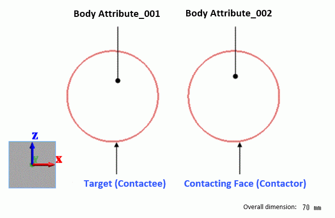
Circular sheet bodies represent objects.
The contactor and contactee surfaces are paired in the “Boundary Pair” dialog box.
Body Attribute and Material Property
|
Body Number/Type |
Body Attribute Name |
Material name |
|
0/Sheet |
Body_Attribute_001 |
001_Al * |
|
1/Sheet |
Body_Attribute_002 |
001_Al * |
* Available from the material DB
The initial velocity of the right object is set as follows. That of the left object is 0 by default.
|
Body Attribute Name |
Initial Velocity |
|
Body_Attribute_001 |
Read distribution |
|
Body_Attribute_002 |
X component: -100[m/s] Y and Z components: 0[m/s] |
Boundary Condition
|
Boundary Condition Name/Topology |
Tab |
Boundary Condition Type |
Setting |
|
Contactor/Edge |
Mechanical |
Contact Surface |
Select “Contactor surface”. |
|
Target/Edge |
Mechanical |
Contact Surface |
Select “Contactee surface”. |
|
Coefficient of friction : 0.4 |
|
|
|
The contactor and contactee surfaces are designated as a contact pair in the “Boundary Pair” dialog box. In contact analyses, the contact surfaces must be designated as a boundary pair.
Results
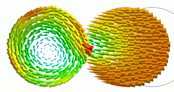
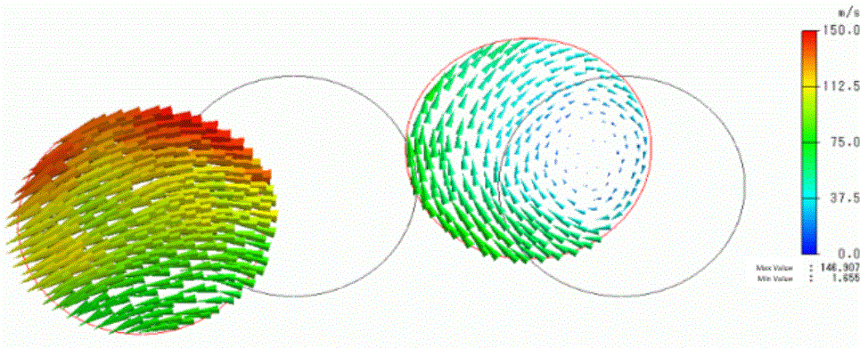
The displacement is shown below. The vectors are velocity. The unit of velocity is [m/s].

The friction with the rotating object causes deformation in the Z direction. The object with an initial velocity rotates after the collision.
On the [Results] tab,
click [Create Animation] ![]() .
.
The animation gives you a visual understanding of the objects’ state before and after the collision.