CAE Software【Femtet】Murata Software Co., Ltd.

Example65 Contact Analysis of Bending Plate

General
-
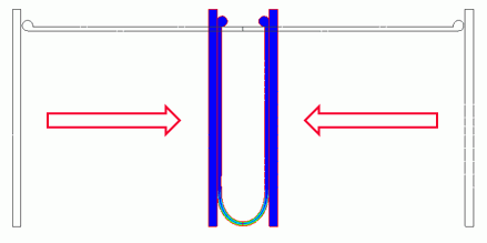
This is an example of a contact analysis of the process of bending a plate into a U-shape by pressing it with other plates from both sides.
-
The deformation, the displacement distribution, and the stress distribution are solved.
-
Unless specified in the list below, the default conditions will be applied.
Analysis Space
|
Item |
Setting |
|
Analysis Space |
2D |
|
Model unit |
mm |
Analysis Condition
“Large Deformation” is selected as the analysis involves the large deformation with rotation.
|
Item |
Setting |
|
Solver |
Stress analysis [Galileo] |
|
Analysis Type |
Static Analysis |
|
Options |
Select Large Deformation |
The Step/Thermal Load is set as follows.
Since the deformation is large, the number of substeps is increased to ensure the convergence of calculation.
|
Tab |
Setting Item |
Setting |
|
Step/Thermal Load |
Step/Reached Temperature Setting |
Number of Substeps : 40 |
| Options for the nonlinear analysis | Select Save the results of substeps |
Model
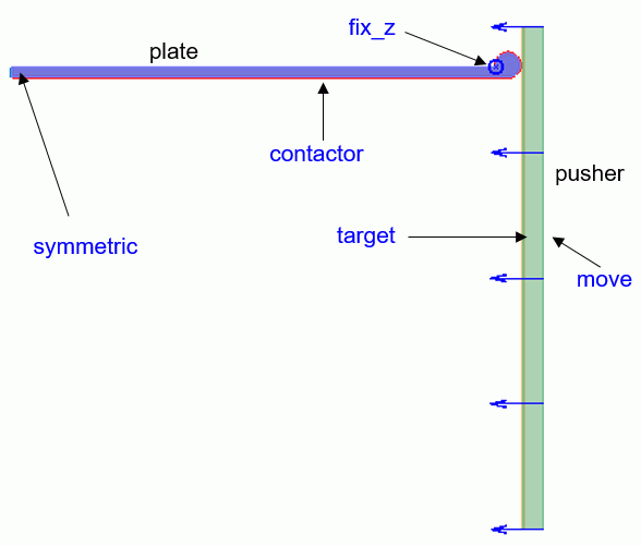
A symmetric boundary (symmetric) and a contactor face (contactor) are set to the plate that is to be bent.
Also, a fixed Z-displacement boundary (fix_z) is set for the stable bending.

The contacting parts are made circular so that the plate bends downward convexly.
The circular form is adjusted so that the initial contact occurs above the fixed Z-displacement boundary (fix_z).
A contactee surface (target) and a displacement boundary (move) are set to the plate that is used for bending the other plate.

Body Attributes and Materials
|
Body Number/Type |
Body Attribute Name |
Material Name |
|
1/Sheet |
pusher |
007_Fe * |
|
3/Sheet |
plate |
001_Al * |
* Available from the material DB
Boundary Condition
The boundary conditions are set as follows.
|
Boundary Condition Name/Topology |
Tab |
Boundary Condition Type |
Setting |
|
fix_z/vertex |
Mechanical |
Displacement |
Select the Z Component. |
|
Move/Edge |
Mechanical |
Displacement |
Select the X and Z components. UX= -45 x 10-3 [m] |
|
contactor/Edge |
Mechanical |
Contact Surface |
Contactor surface |
|
target/Edge |
Mechanical |
Contact Surface |
Contactee surface |
|
Symmetric/Edge |
Symmetry/Continuity |
Symmetry |
Select Reflective |
The contact pair is set as below. The coefficient of friction is set to 0.
|
Boundary Pair |
Coefficient of Friction |
|
contactor-target |
0.0 |
Results
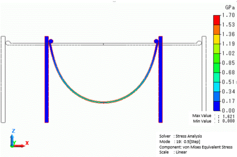
The displacement and the von Mises stress distribution at the step 0.5 are shown below.


The stresses are exhibited over the entire plate body.
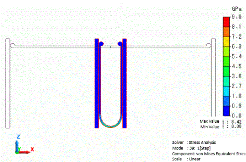
Below are the displacement and the von Mises stress distribution at the step 1.0.


Since the bending deformation of the body is concentrated in the center part, the mechanical stress also occurs in the same part.

