CAE Software【Femtet】Murata Software Co., Ltd.

Example66 Joint Load

General
-
The joint load is applied around a through hole of two plates.
-
The joint load allows you to take into account the forces that pull each other such as axial force due to the bolted connection.
-
Unless specified in the list below, the default conditions will be applied.
Analysis Space
|
Item |
Setting |
|
Analysis Space |
3D |
|
Model Unit |
mm |
Analysis Conditions
|
Item |
Setting |
|
Solver |
Stress analysis [Galileo] |
|
Analysis Type |
Static analysis |
Model
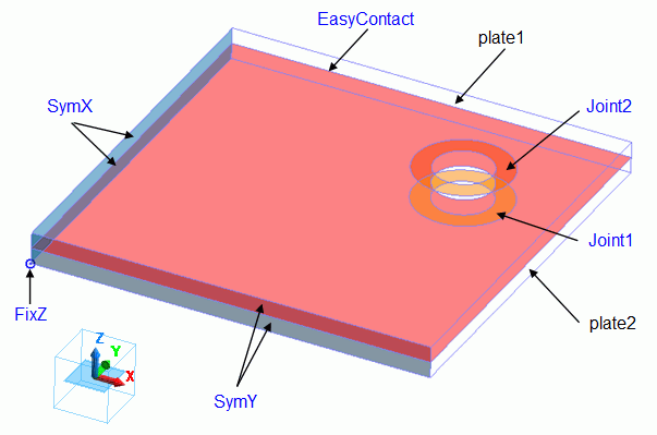
A hole is drilled through the two plates (plate1 and plate2) of 25mm x 25mm.
Circular faces are carved around the through hole to set the joint load boundary conditions (Joint1 and Joint2).
The boundary of the two plates is set simple contact (automatic judgment) boundary condition (EasyContact).
The symmetric boundaries (SymX and SymY) are set to the faces of symmetry of the model to make the symmetric model.
To restrict the Z displacement, the boundary condition (FixZ) which fixes Z displacement is set to the point on the symmetric face.


Body Attributes and Materials
|
Body Number/Type |
Body Attribute Name |
Material Name |
|
3/Solid |
plate1 |
001_Al * |
|
4/Solid |
plate2 |
002_Polycarbonate(PC) * |
* Available from the material DB
Boundary Condition
The boundary conditions are set as follows.
|
Boundary Condition Name/Topology |
Tab |
Boundary Condition Type |
Setting |
|
Joint1/Face |
Mechanical |
Joint load |
|
|
Joint2/Face |
Mechanical |
Joint load |
|
|
EasyContact/Face |
Mechanical |
Simple contact |
Automatic judgment |
|
SymX/Face |
Symmetry/Continuity |
Symmetry |
Select Reflective |
|
SymY/Face |
Symmetry/Continuity |
Symmetry |
Select Reflective |
|
FixZ/Verted |
Mechanical |
Displacement |
Select only Z component. Set it to 0. |
The joint load pair of 1N is set as below.
|
Boundary Pair |
Joint Load |
|
Joint1-Joint2 |
1.0 [N] |
Results
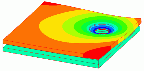
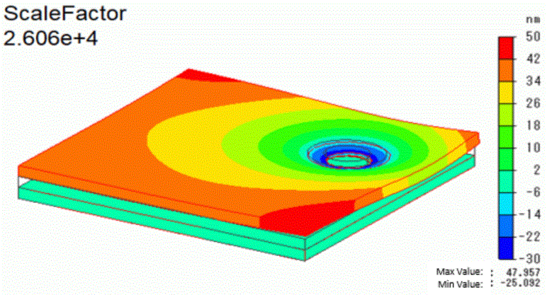
Below is the displacement diagram with color contour of Z component.


For easy viewing, the deformation is scaled up to about 26000.
The joint load caused a depression of about 25nm around the through hole of the polycarbonate plate2.
On the other hand, the area far from the hole is deformed to float up to 48nm.
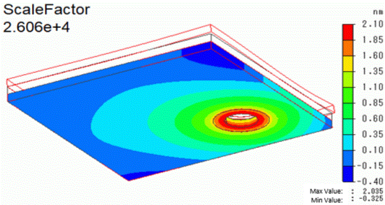
Below is the contour diagram of the aluminum plate1 only.


Although it is smaller compared with the plate2, plate1 also shows the deformation.
It is about 2nm around the through hole.

