CAE Software【Femtet】Murata Software Co., Ltd.

Example67 Spring Connection

General
-
Spring connection of two bodies is analyzed.
-
Spring connection allows you to take into account the load calculated by the relative displacement and the spring constant.
-
Unless specified in the list below, the default conditions will be applied.
Analysis Space
|
Item |
Setting |
|
Analysis Space |
3D |
|
Model Unit |
mm |
Analysis Conditions
|
Item |
Setting |
|
Solver |
Stress analysis [Galileo] |
|
Analysis Type |
Static analysis |
|
Analysis Options |
Select large deformation |
The Step/Thermal Load tab is set as follows. Substeps is changed to 8 from the default of 20.
|
Tab |
Setting Item |
Setting |
||||
|
Step/Thermal Load |
Step/Reached Temperature Setting |
|
Model
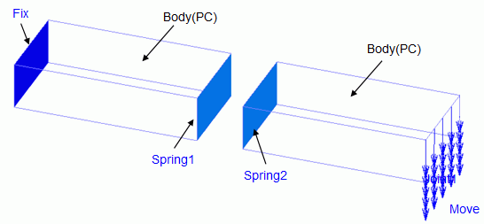
The spring connection boundaries are set between two boxes of 2mm x 2mm x 4mm.
The spring connection boundaries (Spring1 and Spring 2) are set to the body faces and the spring constant is set.
One of the two bodies is set the fixed displacement boundary (Fix), and the other body is set the forced displacement boundary (Move).
This project has two models with different directional components of the forced displacements (Move).


Body Attributes and Materials
|
Body Number/Type |
Body Attribute Name |
Material Name |
|
0/Solid |
Body |
002_Polycarbonate(PC) * |
|
1/Solid |
Body |
002_Polycarbonate(PC) * |
* Available from the material DB
Boundary Condition
The boundary conditions are set as follows.
|
Boundary Condition Name/Topology |
Tab |
Boundary Condition Type |
Setting |
|
Spring1/Face |
Mechanical |
Spring connection |
|
|
Spring2/Face |
Mechanical |
Spring connection |
|
|
Move/Face |
Mechanical |
Displacement |
Select all of X/Y/Z components. model1: UX=0, UY=0, UZ=-1.0e-3 model2: UX=1.0e-3, UY=0, UZ=0 |
|
Fix/Face |
Mechanical |
Displacement |
Select all of X/Y/Z components. UX=0, UY=0, UZ=0 |
The boundary pair is set as below. The spring constant is 1. 0 e5 [N/m].
|
Boundary Pair |
Spring Constant Type and Component Setting |
|
Spring1-Spring2 |
Longitudinal Component 1.0e5 [N/m] |
Results
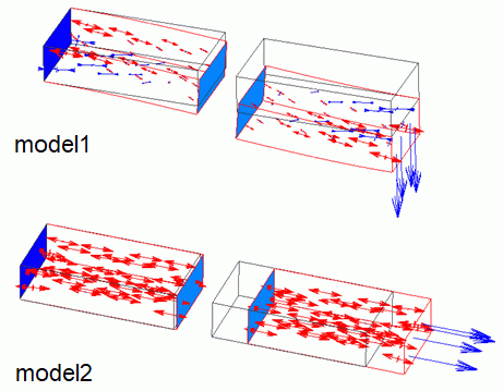
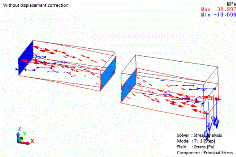
The displacement and the distribution of the principal stress of model1 are shown as below.


The stress can be observed generated by the deformation of the two bodies because of the spring connection.
The force generated by the spring connection is shown in the column of [External/Reactive Force [N]] of the table.
Approximately 12N of force is generated in this model.
The relative displacement of the spring connection boundary faces is about 0.5mm in the Z direction (approximate from the results) except for the bending deformation of the bodies.
The distance between the faces is extended to 1.12mm from 1mm before the deformation.
The elongation of the spring, therefore, is 0.12mm. Multiplying it by the spring constant of 1.0e5[N/m] gives 12N.
It matches the external force on the numerical summary table.
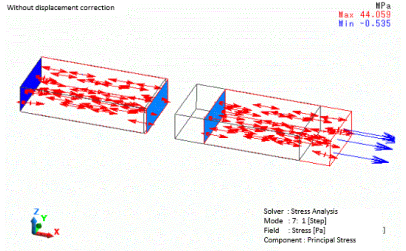
The displacement and the distribution of the principal stress of model2 are shown as below.


The tensile stress can be observed generated by the tensile deformation of the two bodies because of the spring connection.
The force generated by the spring connection is shown in the column of [External/Reactive Force [N]] of the table.
In this model, approximately 85.4N of force is generated.
The relative displacement of the spring connection boundary faces is about 0.854mm in the X direction (approximate from the results) except for the tensile deformation of the bodies.
The distance between the faces is extended to 1.854mm from 1mm before the deformation.
The elongation of the spring, therefore, is 0.854mm. Multiplying it by the spring constant of 1.0e5[N/m] gives 85. 4N.
It matches the external force on the numerical summary table.

