CAE Software【Femtet】Murata Software Co., Ltd.

Example21 Waveguide Analysis of Balanced Line

General
-
The characteristics of a balanced line are analyzed.
-
The differential impedance and the propagation constant are solved.
-
Unless specified in the list below, the default conditions will be applied.
Analysis Space
|
Item |
Settings |
|
Analysis Space |
2D |
|
Model unit |
mm |
Analysis Conditions
|
Item |
Settings |
|
Solvers |
Electromagnetic Analysis [Hertz] |
|
Analysis Type |
Waveguide analysis |
|
Options |
Select “Ignore the influence of face/edge electrode thickness” * |
* This is the default setting. There are no face electrodes with this model. Therefore it is irrelevant to select it or not.
Mesh tab, Harmonic analysis tab and Open boundary tab are set as follows.
|
Tab |
Setting Item |
Settings |
|
|
Meshing Setup |
Deselect Automatically set the general mesh size * General mesh size: 0.2[mm] |
|
Mesh Tab |
Frequency-Dependent Meshing |
Reference frequency: 1×10^9[Hz] Select “The conductor bodies thicker than the skin depth constitute the boundary condition.” |
|
Waveguide analysis |
Frequency |
Minimum: 1×10^9[Hz] Maximum: 1×10^9[Hz] |
|
Sweep Type |
Select Linear step Division number: 0 |
|
|
The maximum number of propagation modes |
2 |
* The general mesh size is a bit too large in this exercise. Smaller mesh size is set.
Model
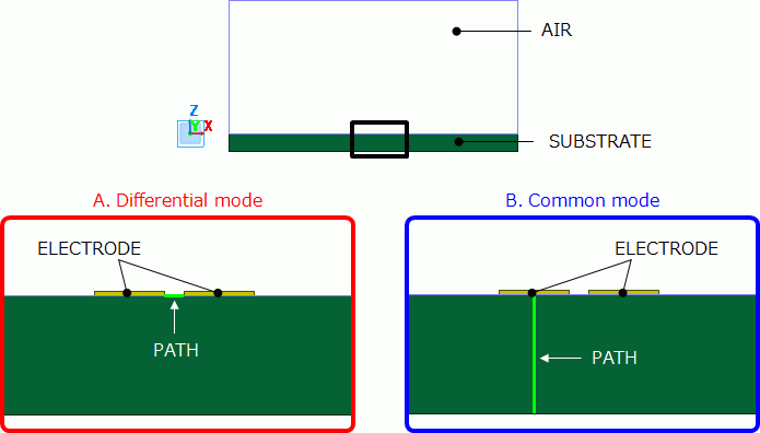
Two electrodes are created on a substrate. They function as a balanced line.
They are covered with rectangle air space.
Setting place of the wire body for integral path (PATH) depends on the mode to analyze.
For the differential mode analysis, place the wire body between the electrodes as in the diagram A.
For the common mode analysis, place the wire body between one of the electrodes and the ground as in the diagram B.

Body Attributes and Materials
|
Body Number/Type |
Body Attribute Name |
Material Name |
|
0/Sheet |
SUBSTRATE |
006_Glass_epoxy * |
|
1/Sheet |
ELECTRODE |
008_Cu * |
|
2/Sheet |
ELECTRODE |
008_Cu * |
|
3/Sheet |
AIR |
000_Air(*) |
|
4/Wire |
|
|
* Available from the Material DB
Boundary Conditions
|
Boundary Condition Name/Topology |
Tab |
Boundary Condition Type |
|
Outer Boundary Condition |
Electric |
Electric wall |
|
PATH |
Electric |
Integral path |
Results
1. Propagation Mode
As the maximum number of the propagation modes is set to 2 in the analysis condition,
two propagation modes are calculated for one frequency.
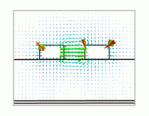
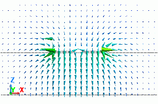
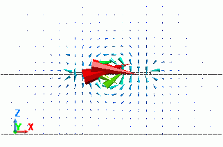
Regardless of the integral path location, electric fields of two modes are as follows
From the shapes of the electric fields, you can tell that the first mode is the common mode and the second mode is the differential mode.
|
Mode |
Electric Field |
|
0: 1.000000e+09[Hz](0) |
|
|
1: 1.000000e+09[Hz](1) |
|
2. Characteristic Impedance
On the Characteristic impedance (Zpv)[ohm] tab in Table, you can check the characteristic impedance.
The following diagram shows the characteristic impedance obtained for the models with integral path locations A and B above.
Please note that calculation of the characteristic impedance of the common mode is inaccurate if the integral path location A is used which is for the differential mode analysis.
Also, calculation of the characteristic impedance of the differential mode is inaccurate if the integral path location B is used which is for the common mode analysis.
|
Mode |
Integral Path Location A |
Integral Path Location B |
|
0: 1.000000e+09[Hz](0) (Common mode) |
1.307 Ω (inaccurate) |
60.754 Ω |
|
1: 1.000000e+09[Hz](1) (Differential mode) |
93.237 Ω |
23.196 Ω (inaccurate) |
3. Propagation Constant
Unlike characteristic impedance, propagation constant is not affected by the location of integral path.
Propagation constant tab in Table, you can check the propagation constant as follows.
Regardless of the integral path location, the same values are calculated.
|
Mode |
Integral Path Location A |
Integral Path Location B |
|
0: 1.000000e+09[Hz](0) (Common mode) |
Attenuation constant: 0.236 Np/m |
Attenuation constant: 0.239 Np/] |
|
1: 1.000000e+09[Hz](1) (Differential mode) |
Attenuation constant: 0.408 Np/m |
Attenuation constant: 0.424 Np/m |


