
CAE Software【Femtet】Murata Software Co., Ltd.
Example25 Antenna
General
-
The impedance characteristics of a loop antenna are solved.
-
Unless specified in the list below, the default conditions will be applied.
Analysis Space
|
Item |
Setting |
|
Analysis Space |
3D |
|
Modelunit |
m |
Analysis Conditions
|
Item |
Setting |
|
Solver |
Electromagnetic Analysis [Hertz] |
|
Analysis Type |
Harmonic Analysis |
|
Options |
Select “Ignore the influence of face/edge electrode thickness” * |
* This is the default setting. It is irrelevant to select it or not as there are no face electrodes with this model.
Harmonic Analysis tab and Open Boundary tab are set as follows.
|
Tab |
Setting Item |
Setting |
|
Mesh |
Frequency-Dependent Meshing |
Reference frequency: 13.56×10^6[Hz] Select “The conductor bodies thicker than the skin depth constitute the boundary condition.”
As Metal is thicker than the skin depth, boundary condition with copper material loss is applied to the Metal surface. |
|
Meshing Control |
Tessellations of Periodic Surface Minimum number of tessellations: 12 Loop antenna’s circular shape is approximated as a polygon. Minimum number of tessellations is 6 by default. That is a hexagon. To increase the accuracy, it is changed to 12. That is a dodecagon. |
|
|
Harmonic Analysis |
Frequency |
Minimum: 12×10^6[Hz] Maximum: 14×10^6[Hz] |
|
Sweep Type |
Select Linear step by division number. Division number: 50 |
|
|
Sweep Setting |
Select Discrete sweep |
|
|
Input |
1.0[W] |
|
|
Open Boundary |
Type |
Absorbing boundary |
|
Order of Absorbing Boundary |
1st degree |
Fast sweep is avoided for higher accuracy.
Graphical Objects
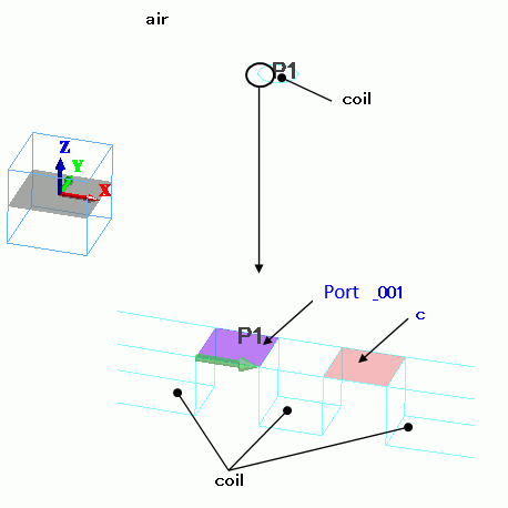
Loop antenna consists of solid bodies. A port and a lumped-constant C are placed on it.
They are sheet bodies set with boundary conditions.
The antenna is covered with spherical air, AIR. Its radius is 6m. 6m is 13MHz and about a quarter of the wavelength.
Open boundary is set on the surface of AIR.
Body Attributes and Materials
|
Body Number/Type |
Body Attribute Name |
Material Name |
|
3/Solid |
coil |
008_Cu (*) |
|
5/Solid |
coil |
008_Cu (*) |
|
14/Sheet Body |
Imprinting body |
|
|
15/Sheet Body |
Imprinting body |
|
|
16/Solid |
air |
000_Air(*) |
(*) Available from the Material DB
Boundary Conditions
|
Boundary Condition Name/Topology |
Tab |
Boundary Condition Type |
Setting |
|
Port_001/Face |
Electric |
I/O Port |
Reference Impedance: select Specify enter 50Ω. Number of Modes: number of precalculated modes: 5 number of modes used in the actual analysis: 1 Select modes: none |
|
C/Face |
Electric |
Lumped constant |
Capacitance: 20.65×10^-12[F] |
|
Outer Boundary Condition |
Electric |
Open boundary |
Select on the open boundary tab of the analysis condition setting. |
Results
The impedance characteristic is shown below. The center of Smith chart is 50[Ohm]. S-parameter S11 is shown in the right graph below.
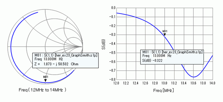
The reflected power is large in the S-parameter S11 graph. We will reduce the reflected power by changing the reference impedance of the port as follows. Impedance at 13GHz is 1.873-j50.502[Ω] in the Smith chart above. To reduce the reflected power, set the reference impedance at (1.873+j50.502[Ω]) which is the conjugate value. The result is shown in the graph below. As the impedance at 13MHz is used as a reference impedance, we can see the matching at 13MHz.
-
To obtain the same result as shown here, pay attention to the following points. Use the same meshes before and after changing the reference impedance. If the reference impedance is changed, meshes created by the adaptive mesh will also be changed. Create a new project before changing the reference impedance and analyze with the existing mesh. Specify the pdt file of the project with the reference impedance before changing.

-
See [Exercise 7: Dipole Antenna] for the details of the radiation patterns and settings.