CAE Software【Femtet】Murata Software Co., Ltd.

Example41 Frequency-Selective Reflector
General
-
Analyzed is a frequency-selective reflector that allows specific electromagnetic waves pass through.
-
The port size is large relative to the wavelength (about 10 times the wavelength).
-
Unless specified in the list below, the default conditions will be applied.
Analysis Space
|
Item |
Setting |
|
Analysis Space |
3D |
|
Model Unit |
mm |
Analysis Condition
|
Item |
Setting |
|
Solver |
Electromagnetic analysis [Hertz] |
|
Analysis Type |
Harmonic analysis |
|
Tab |
Setting Item |
Setting |
|
Mesh |
Frequency-Dependent Meshing |
Reference frequency: 77[GHz] Select The conductor bodies thicker than the skin depth constitute the boundary condition |
|
Harmonic Analysis |
Sweep Type |
Select “Linear step by division number”. |
|
Sweep Setting |
Minimum frequency: 40[GHz] Maximum frequency: 90[GHz] Division Number: 200 |
|
|
Frequency Sweep |
Select Fast sweep S-parameter tolerance: 1×10⁻³ |
Model
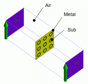
The model consists of a frequency-selective reflector and the air.
The dielectrics (Sub) are placed on the conductive plate (Metal) and encircled by curved slits.

Body Attributes and Materials
|
Body Number/Type |
Body Attribute Name |
Material Name |
|
5, 30, 31, 32, 33, 34, 35, 36, 37/Solid |
Sub |
006_Glass_epoxy * |
|
38/Solid |
Air |
000_Air * |
|
39, 40, 41, 42, 43, 44, 45, 46, 47, 48/Solid |
Metal |
008_Cu (*) |
* Available from the material DB
Boundary Condition
|
Boundary Condition Name/Topology |
Tab |
Boundary Condition Type |
Setting |
|
Port_001/Face |
Electric |
Port |
Select Reference Impedance:
Integral path Set Path1 |
|
Port_002/Face |
Electric |
Port |
Reference Impedance:
Integral path Set Path1 |
|
EW/Face |
Electric |
Electric wall |
|
|
Outer Boundary Condition |
Electric |
Magnetic wall |
|
Set up Mesher/Solver
|
Setting Item |
Setting |
|
Frequency-Dependent Meshing |
Reference frequency: 77[GHz] Select The conductor bodies thicker than the skin depth constitute the boundary condition |
Results
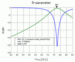
S-parameters are shown below. The transmission characteristic is observed at around 77GHz.

Shown below is the current density at 40GHz (transmission characteristic does not appear) and at 77GHz (transmission characteristic appears) on the frequency-selective reflector.

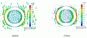
At 40GHz, the current is flowing in the entire area of the conductor whereas the current is concentrated near the slit at 77GHz.
Its value is large.
The electromagnetic field that causes the concentrated current near the slit is the resonant mode of the frequency-selective reflector. The resonant mode generates the transmission characteristic at a specific frequency.
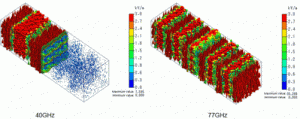
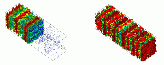
The figures below show the electric fields at 40GHz and 77GHz. At 40GHz, the incident electromagnetic wave is blocked by the frequency-selective reflector and not transmitted.
At 77GHz, the electromagnetic wave is transmitted through the frequency-selective reflector.
For a clear comparison, the scale factor for drawing vectors is set to 10, and the maximum value is set to 3k[V/m].
