CAE Software【Femtet】Murata Software Co., Ltd.

Example43 Ground-Penetrating Radar
General
-
A ground-penetrating radar with an exponential TEM horn antenna is analyzed.
-
How the electromagnetic waves transmitted from the transmitter are received at the receiver can be viewed by the output voltage and result field.
-
By comparing the results with and without a foreign matter, how the received voltage detects the foreign matter is verified.
-
Unless specified in the list below, the default conditions will be applied.
-
Electromagnetic-transient analysis is available in an optional package.
Analysis Space
|
Item |
Setting |
|
Analysis Space |
3D |
|
Model Unit |
m |
Analysis Condition
With this model, it is necessary to trace the propagation of electromagnetic waves by several wavelengths, and the analysis size becomes large. So the 1st-order elements are used to reduce calculation time.
|
Item |
Setting |
|
Solver |
Electromagnetic analysis [Hertz] |
|
Analysis Type |
Transient analysis
Select Input at each port |
|
Tab |
Setting Item |
Setting |
|
Mesh |
General mesh size |
0.05[m] |
|
Element Type |
1st-Order Element |
|
|
Frequency-Dependent Meshing |
Select The conductor bodies thicker than the skin depth constitute the boundary condition Select Determine the reference frequency automatically from the input waveform |
|
|
Transient analysis |
Waveform Type |
Broadband Pulse
Minimum frequency: 0.5[Hz] Maximum frequency: 1.0[Hz] |
|
Finish time of calculation |
2.0×10⁻⁸ [s] |
|
|
Output Field *1 |
Select Output Field
Output Interval for Field: 1 |
*1 If you want to reduce the result size, increase the Output Interval for Field or deselect Output Field.
If the fields are not output, only the table values are output.
Model
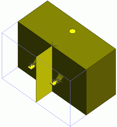
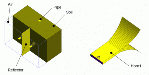
The model consists of an exponential TEM horn antenna (Horn1 and Horn2), which is a transmitting and receiving antenna, a reflecting object (Reflector) with an electric wall which is intended to avoid noise due to direct wave reception and diffraction,
an air domain (Air), soil, and a conductive pipe (Pipe) as a foreign body.

Body Attributes and Materials
|
Body Number/Type |
Body Attribute Name |
Material Name |
|
0, 1/Sheet |
Horn1 |
001_Al * |
|
2, 3/Sheet |
Horn2 |
001_Al * |
|
4/Solid |
Air |
000_Air * |
|
6/Solid |
Pipe |
008_Cu (*) |
|
10/Solid |
Soil |
Soil |
* Available from the material DB
The material properties of Soil are set up as follows.
|
Material Name |
Tab |
Properties |
|
Soil |
Permittivity |
Relative permittivity: 2.0 |
|
Conductivity |
Conductor
Conductivity: 1.0×10⁻³ [S/m] |
Boundary Condition
|
Boundary Condition Name/Topology |
Tab |
Boundary Condition Type |
Setting |
|
Port1/Face |
Electric |
Port |
Reference Impedance:
Integral Path: Set Path1 |
|
Port2/Face |
Electric |
Port |
Reference Impedance:
Integral Path: Set Path1 |
|
Reflector/Face |
Electric |
Electric wall |
|
|
Outer Boundary Condition |
Electric |
Open boundary |
|
Results
The transient analysis result of the output voltage is shown by red line.

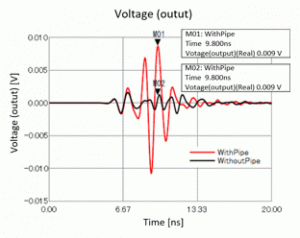
For comparison, the result of analysis without foreign body (WithoutPipe) is shown by black line. As the graph shows, the analysis with a foreign body has a large signal reception
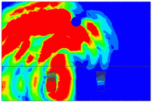
at around 10ns. It indicates that the electromagnetic waves from the transmitting antenna (Port1) are reflected by the conductive pipe and propagate to the receiving antenna (Port2).
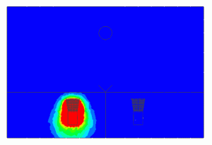
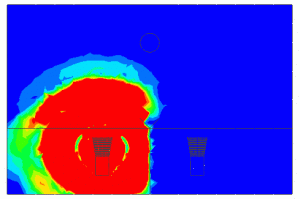
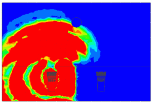
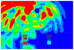
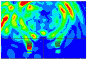
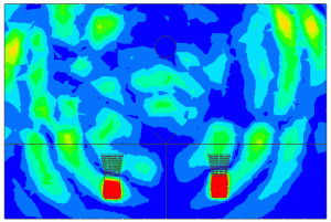
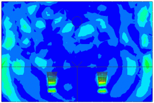
The figures below are electric field contours of the XY cross section. From these figures too, it can be viewed how the electromagnetic waves from the transmitting antenna are reflected by the conductive pipe and propagate to the receiving antenna.
For clear comparison, the maximum value of the electric field is fixed at 0.5[V/m] in the graphics setup.
|
Time [s] |
Electric Field Contour |
|
2ns |
|
|
4ns |
|
|
5ns |
|
|
6ns |
|
|
7ns |
|
|
8ns |
|
|
9ns |
|
|
10ns |
|


