CAE Software【Femtet】Murata Software Co., Ltd.

Example2 Torque Analysis of SPM Motor
General
-
Torque characteristics of SPM motor (Surface Permanent Magnet Motor) is analyzed when the electricity is applied.
The model is a permanent magnet synchronous motor with magnets attached on the surface of a rotor. -
The analysis is coupled with the external circuit.
-
The homogenizing method is applied to simulate the layer structure of the electromagnetic plates of steel for the core.
-
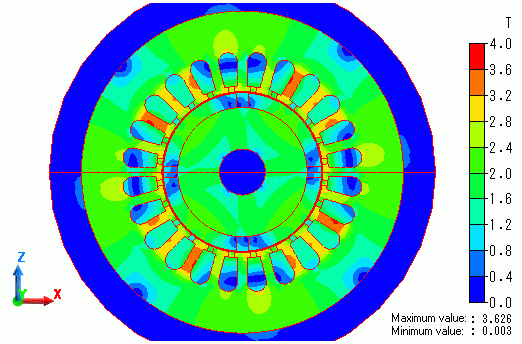
The torque and the magnetic flux density are solved.
-
Unless specified in the list below, the default conditions will be applied.
-
In this exercise, the model is half period symmetric for your easy understanding.
Fast calculation is possible by making this model 1/4 period symmetric.
Obtain this session’s project file. (Save the project file before open)
Analysis Conditions
|
Item |
Settings |
|
Solvers |
Magnetic Field Analysis [Luvens] |
|
Analysis Space |
2D |
|
Analysis Type |
Transient Analysis |
|
Unit |
mm |
|
Options |
Select External Circuit Coupling. Select Rotating machinery.
[Conversion] Model Thickness: 30×10^-3[m] Select Partial Model. Number of Divisions of the Whole Model: 2 Circuit Configuration Number of Series: 1 Circuit Configuration Number of parallels: 2 Select Convert the result to the whole model and output it. |
The Rotating Machinery tab is set as follows.
|
Tab |
Setting Item |
Setting |
|
Rotating Machinery |
Rotational Movement |
Select Constant Velocity. Number of Rotations: 1800[r/min] Rotor’s Initial Rotation Position: 0[deg] |
|
Number of Slide Mesh Divisions |
Circumferential Division Angle: 1.0[deg] Rotation per Step: 1[mesh] Number of Slide Mesh Layers: 3 |
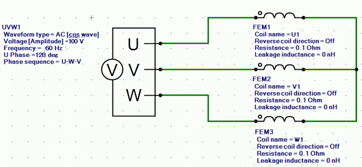
External circuit is as follows.
60[Hz] three-phase AC voltage is applied.
Set the Mesh Tab as follows.
|
Tab |
Setting Item |
Setting |
|
Mesh |
Meshing Setup |
Automatically set the general mesh size: Deselect General mesh size: 1[mm] |
|
Ambient Air Creation |
Select Create ambient air automatically. Ambient Air Scale: 1.2 |
The Transient Analysis tab is set up as follows.
With the settings as below, number of steps is 180, circumferential division angle is 1.0[deg], and rotation per step is 1[mesh], the rotation up to 180 degrees (=180*1.0*1) is analyzed.
|
Tab |
Setting Item |
Setting |
|||||
|
Transient Analysis |
Time step |
Automatic |
|||||
|
Table |
|
Graphical Objects
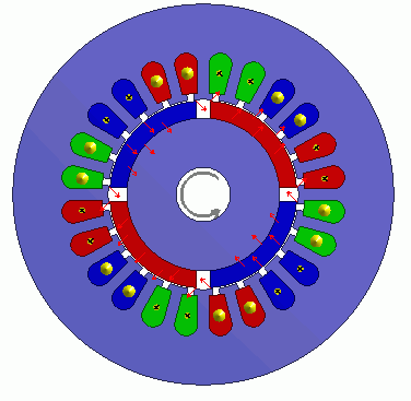
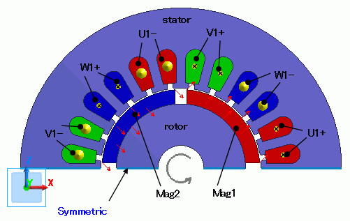
A rotor core and magnet are placed in the center. A stator and coils are placed around them.
The motor has 4 poles.
This is a 2D model analysis. By utilizing the symmetry of the analysis model, it is made to be a half period symmetric model.
Rotation period boundary (symmetric) is set.
“Ambient Air Creation” is selected.
-
In this exercise, the model is half period symmetric for your easy understanding. The calculation can be faster by making this model quarter period symmetric.
In the quarter model, the number of series in the circuit is 2 and the resistance value of FEM coil in the external circuit is half of the half model.
Body Attributes and Materials
|
Body Number/Type |
Body Attribute Name |
Material Name |
|
4/Sheet |
Mag1 |
mag |
|
5/Sheet |
Mag2 |
mag |
|
0/Sheet |
Rotor |
core |
|
27/Sheet |
Stator |
core |
|
29/Sheet |
U1+ |
Cu |
|
30/Sheet |
U1+ |
Cu |
|
31/Sheet |
W1- |
Cu |
|
32/Sheet |
W1- |
Cu |
|
33/Sheet |
V1+ |
Cu |
|
34/Sheet |
V1+ |
Cu |
|
35/Sheet |
U1- |
Cu |
|
36/Sheet |
U1- |
Cu |
|
37/Sheet |
W1+ |
Cu |
|
38/Sheet |
W1+ |
Cu |
|
39/Sheet |
V1- |
Cu |
|
40/Sheet |
V1- |
Cu |
The material properties are set up as follows:
The homogenizing method is applied to simulate the laminated plate of steel for the core.
|
Body Attribute Name |
Tab |
Setting |
|
Mag1 |
Direction |
Vector: X=1, Y=0, Z=1 |
|
Stator/Rotor/Air |
Rotor |
|
|
Mag2 |
Direction |
Vector: X=1, Y=0, Z=-1 |
|
Stator/Rotor/Air |
Rotor |
|
|
Rotor |
Layer |
Select Take layer into account Space Factor: 97[%] Layer Direction Vector: X=0, Y=1, Z=0 |
|
Stator/Rotor/Air |
Rotor |
|
|
Stator |
Layer |
Select Take layer into account Space Factor: 97[%] Layer Direction Vector: X=0, Y=1, Z=0 |
|
Stator/Rotor/Air |
Stator |
|
|
U1- |
Current |
Waveform: External Circuit Coupling Coil name on the circuit: U1 Turns: 35[Turns] Direction: – Y Direction |
|
Stator/Rotor/Air |
Stator |
|
|
U1+ |
Current |
Waveform: External Circuit Coupling Coil name on the circuit: U1 Turns: 35[Turns] Direction: +Y Direction |
|
Stator/Rotor/Air |
Stator |
|
|
V1- |
Current |
Waveform: External Circuit Coupling Coil name on the circuit: V1 Turns: 35[Turns] Direction: – Y Direction |
|
Stator/Rotor/Air |
Stator |
|
|
V1+ |
Current |
Waveform: External Circuit Coupling Coil name on the circuit: V1 Turns: 35[Turns] Direction: +Y Direction |
|
Stator/Rotor/Air |
Stator |
|
|
W1- |
Current |
Waveform: External Circuit Coupling Coil name on the circuit: W1 Turns: 35[Turns] Direction: – Y Direction |
|
Stator/Rotor/Air |
Stator |
|
|
W1+ |
Current |
Waveform: External Circuit Coupling Coil name on the circuit: W1 Turns: 35[Turns] Direction: +Y Direction |
|
Stator/Rotor/Air |
Stator |
The material properties are set as follows.
|
Material Name |
Tab |
Properties |
||||||||||||||||||||||
|
Cu |
Conductivity |
Conductivity Type: Conductor Conductivity: 5.977×10^7[S/m] |
||||||||||||||||||||||
|
mag |
Relative permeability |
Material Type: Permanent Magnet |
||||||||||||||||||||||
|
Magnet |
Magnetization Characteristic Type: Linear Magnetization Strength: 1.25[T] Relative Permeability: 1.05 |
|||||||||||||||||||||||
|
core |
Permeability |
Magnetization Characteristic Type: Select B-H curve B-H Curve Table
|
Boundary Conditions
Half period symmetric boundary is set.
|
Boundary Condition Name/Topology |
Tab |
Boundary Condition Type |
Setting |
|
Symmetric |
Symmetry/Continuity |
Periodic |
Rotation Period (1 period) |
Results
The distribution of the magnetic flux density at the rotation angle of 0[deg] is shown below.
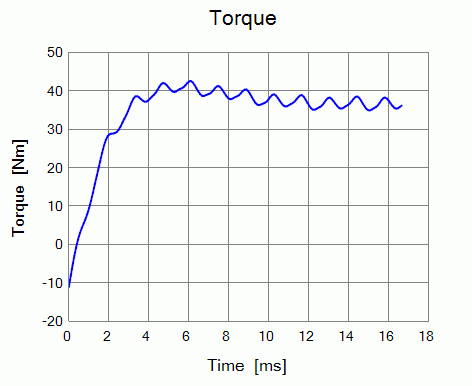
The diagram below shows time-torque characteristics.
Transient state becomes stable at around 12[ms].
About 40[N*m] of torque is obtained.
