CAE Software【Femtet】Murata Software Co., Ltd.

Example14 Analysis of Induction Motor with Specified Rotating Speed
General
-
A cage structure 3-phase induction motor is analyzed.
The magnetic field of coils of the stator generates the eddy current on the conductor of the rotor.
The magnetic field generated by the eddy current and the magnetic field on the stator create the torque which rotates the asynchronous motor. -
The rotating speed is specified.
By changing the rotating speed, how the torque is changed can be analyzed.
Example 4 analyzes the same analysis model without specifying the rotating speed. -
The torque and the magnetic flux density are solved.
-
Unless specified in the list below, the default conditions are applied.
Analysis Condition
|
Item |
Setting |
|
Analysis Space |
2D |
|
Thickness in Depth Direction |
42[mm] |
|
Unit |
mm |
|
Solver |
Magnetic Analysis [Luvens] |
|
Analysis Type |
Transient Analysis |
|
Analysis Options |
Select External Circuit Coupling. Select Rotating machinery.
[Partial Model (Symmetric Model) Setting] Select Partial Model. Division number: 2 [Conversion of external circuit I/O values] Select Convert Number of series: 1 Number of parallels: 2 Select Convert the result to the full model for output |
The Rotating Machinery tab is set as follows.
|
Tab |
Setting Item |
Setting |
|
Rotating Machinery |
Rotational Movement |
Select Constant Velocity The Number of Rotations: 1267[r/min] Rotor’s Initial Rotation Position: 0[deg] |
|
Number of Sliding Mesh Divisions |
Circumferential Division Angle: 0.5[deg] Number of Sliding Mesh Layers: 3 |
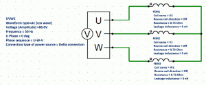
External circuit is as follows.
50[Hz] 3-phase AC voltage is applied.

Set the Mesh Tab as follows.
|
Tab |
Setting Item |
Setting |
|
Mesh |
Meshing Setup |
Set the general mesh size automatically: Deselect General Mesh size: 2[mm] |
|
Automatic Ambient Air Creation |
Select Create ambient air automatically Ambient Air Scale: 1.2 |
The Transient Analysis tab is set up as follows.
One second is divided into 800 steps.
|
Tab |
Setting Item |
Setting |
|||||
|
Transient Analysis |
Timestep |
Automatic |
|||||
|
Table |
|
Model
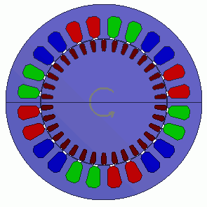
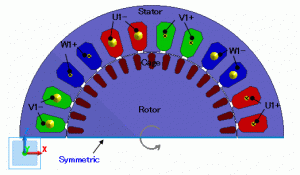
A rotor cage consisted of conductor and rotor core is placed in the center. A stator core and coils are placed around it.
This is a 2D model analysis. By utilizing the symmetry of the analysis model, it is made to be a half period symmetric model.
“Ambient Air Creation” is selected.
Small mesh size is (0.3mm) is applied to the gap.

Body Attributes and Materials
|
Body Number/Type |
Body Attribute Name |
Material Name |
|
25/Sheet |
Cage |
Al |
|
26/Sheet |
Cage |
Al |
|
27/Sheet |
Cage |
Al |
|
28/Sheet |
Cage |
Al |
|
29/Sheet |
Cage |
Al |
|
30/Sheet |
Cage |
Al |
|
31/Sheet |
Cage |
Al |
|
32/Sheet |
Cage |
Al |
|
33/Sheet |
Cage |
Al |
|
34/Sheet |
Cage |
Al |
|
35/Sheet |
Cage |
Al |
|
36/Sheet |
Cage |
Al |
|
37/Sheet |
Cage |
Al |
|
38/Sheet |
Cage |
Al |
|
39/Sheet |
Cage |
Al |
|
40/Sheet |
Cage |
Al |
|
41/Sheet |
Cage |
Al |
|
24/Sheet |
Rotor |
50A1300 |
|
65/Sheet |
Stator |
50A1300 |
|
67/Sheet |
U1+ |
Cu |
|
68/Sheet |
U1+ |
Cu |
|
69/Sheet |
W1- |
Cu |
|
70/Sheet |
W1- |
Cu |
|
71/Sheet |
V1+ |
Cu |
|
72/Sheet |
V1+ |
Cu |
|
73/Sheet |
U1- |
Cu |
|
74/Sheet |
U1- |
Cu |
|
75/Sheet |
W1+ |
Cu |
|
76/Sheet |
W1+ |
Cu |
|
77/Sheet |
V1- |
Cu |
|
78/Sheet |
V1- |
Cu |
The body attribute is set up as follows.
|
Body Attribute Name |
Tab |
Setting |
|
Cage |
Stator/Rotor/Air |
Rotor |
|
Rotor |
Stator/Rotor/Air |
Rotor |
|
Stator |
Stator/Rotor/Air |
Stator |
|
U1- |
Current |
Waveform: External circuit coupling Coil name on the circuit: U1 Turns: 66[Turns] Direction: – Y direction |
|
Stator/Rotor/Air |
Stator |
|
|
U1+ |
Current |
Waveform: External circuit coupling Coil name on the circuit: U1 Turns: 66[Turns] Direction: +Y direction |
|
Stator/Rotor/Air |
Stator |
|
|
V1- |
Current |
Waveform: External circuit coupling Coil name on the circuit: V1 Turns: 66[Turns] Direction: – Y direction |
|
Stator/Rotor/Air |
Stator |
|
|
V1+ |
Current |
Waveform: External circuit coupling Coil name on the circuit: V1 Turns: 66[Turns] Direction: +Y direction |
|
Stator/Rotor/Air |
Stator |
|
|
W1- |
Current |
Waveform: External circuit coupling Coil name on the circuit: W1 Turns: 66[Turns] Direction: – Y direction |
|
Stator/Rotor/Air |
Stator |
|
|
W1+ |
Current |
Waveform: External circuit coupling Coil name on the circuit: W1 Turns: 66[Turns] Direction: +Y direction |
|
Stator/Rotor/Air |
Stator |
The material properties are set as follows.
|
Material Name |
Tab |
Properties |
||||||||||||||||||||||||||||||||||||||||||||||||||||||||||||||||||||||||||||||||||
|
Al |
Conductivity |
Conductivity Type: Conductor Conductivity: 1.02×10⁷[S/m] |
||||||||||||||||||||||||||||||||||||||||||||||||||||||||||||||||||||||||||||||||||
|
Cu |
Conductivity |
Conductivity Type: Conductor Conductivity: 5.977×10⁷[S/m] |
||||||||||||||||||||||||||||||||||||||||||||||||||||||||||||||||||||||||||||||||||
|
50A1300 |
Permeability |
Magnetization Characteristic Type: Select B-H curve B-H Curve Table
|
Boundary Condition
Symmetric period boundary is set.
|
Boundary Condition Name/Topology |
Tab |
Boundary Condition Type |
Setting |
|
Symmetric |
Symmetry/Continuity |
Periodic |
Rotation Period (1 period) |
Results
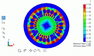
The distribution of the magnetic flux density and magnetic flux lines at the rotation angle of 0 [deg] are shown below.

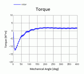
The wave of torque is shown as follows. It is output to “Torque [N*m]” of the result table.

