


|
Home / Simulation Accuracy Setting (Mesh/Element) / Meshing Setup / Adaptive Mesh Setting
Adaptive Mesh Setting
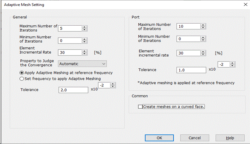
The adaptive mesh method creates finer meshes based on the error energy calculated from the simulation results for the individual elements. The larger elements are divided into the finer meshes.
The number of meshes increases at the given rate after each calculation. If the element incremental rate is 30%, the number of meshes will increase approximately 30% each time.
This process is repeated until the specified physical constant reaches the given accuracy or the iterations reaches the maximum number of iterations.
The calculation will be repeated up to the minimum number of iterations, no matter what.
The physical constants to judge the convergence are listed below. If "Automatic" is selected, the physical constant described first in the list is used.
However, if there is no coil existing in the model of the magnetostatic analysis for example, the inductance cannot be defined. In such a case, the magnetic energy is used for the physical constant which is described second in the list.
|
Solver |
Analysis Type |
Physical Constant to Judge the Convergence |
|
Electric Analysis |
Static Analysis (dielectric material) |
Capacitance/Relative error energy/Absolute error energy |
|
Static Analysis (conductor) |
Resistance/Relative error energy/Absolute error energy |
|
|
Harmonic Analysis |
Admittance/Relative error energy/Absolute error energy |
|
|
Magnetic Analysis |
Static Analysis |
Inductance/Magnetic energy/Relative error energy/Absolute error energy |
|
Harmonic Analysis |
Magnetic energy/Relative error energy/Absolute error energy |
|
|
Electromagnetic Analysis |
Waveguide Analysis |
Characteristic impedance/Propagation constant/Relative error energy/Absolute error energy |
|
Harmonic Analysis |
S-parameters/Relative error energy/Absolute error energy |
|
|
Stress Analysis |
Static Analysis |
Strain energy/Relative error energy/Absolute error energy |
|
Harmonic Analysis |
||
|
Thermal Analysis |
Static analysis
|
Average temperature Maximum temperature Relative value of error energy/Absolute value of error energy |
|
Piezoelectric Analysis |
Static Analysis |
Impedance/Relative error energy/Absolute error energy |
|
Harmonic Analysis |
||
|
Acoustic Analysis |
Harmonic Analysis |
Radiation impedance/Acoustic energy/Relative error energy/Absolute error energy |
-
When the S-parameters are used, the calculation is judged converged if the equation below is true.
|Sijn-Sijn-1| / Smaxn< Accuracy
where Sijn is the S-parameters expressed by the complex numbers, and i and j represent the ports and n represents the iteration numbers of the adaptive meshes.
Smaxn is a real number representing the largest of the S-parameters Sijn acquired in the nth adaptive meshing.
Smaxn = max{ |Sijn| }
-
Like S-parameters, convergence is judged in the same way for the capacitance matrix and the inductance matrix.
Frequency Setting for the Adaptive Mesh in the Electromagnetic-Harmonic Analysis
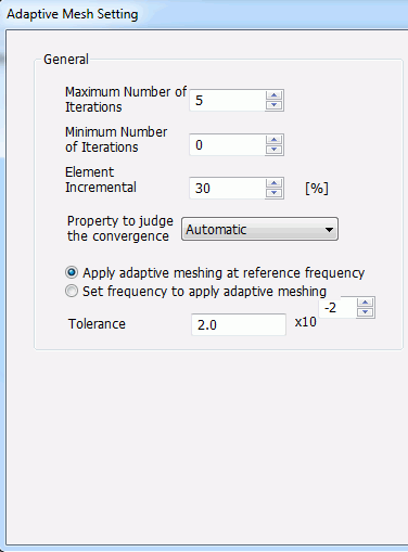
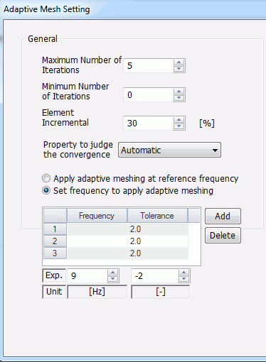
Adaptive mesh creates optimized meshes at a certain frequency.
In the harmonic electromagnetic analysis, either reference frequency or one other than reference frequency can be used for the adaptive mesh of the whole analysis domain.
If the reference frequency is used, select Apply adaptive meshing at reference frequency.
In this case, set an Accuracy to judge the convergence of the adaptive mesh.
If a frequency other than reference frequency is used, select Set frequency to apply adaptive meshing.
In this case, set the Frequency and Accuracy to judge the adaptive mesh convergence at the frequency.
Multiple combinations of frequency and accuracy can be set.
Adaptive Mesh of the Port in the Harmonic Electromagnetic Analysis
For the electromagnetic-harmonic analysis, the adaptive meshing is applied to the ports prior to the adaptive meshing of the entire analysis domain.
The physical constant used to judge the adaptive mesh convergence of the port is automatically selected depending on the port structure, and it cannot be changed.
The physical constants automatically selected are as follows.
-
Waveguide: Propagation constant
-
If the integral path is defined: Characteristic impedance obtained from the voltage
-
If the integral path is not defined: Characteristic impedance obtained from the current
Adaptive mesh cannot be applied with frequencies other than the reference frequency.
Create meshes on a curved face
If selected, additional nodes are created on the curved face. If not selected, additional nodes are created on the initial meshing plane.
Selected by default. Only for the electromagnetic solver, not selected by default.