


|
Home / Simulation Accuracy Setting (Mesh/Element) / Meshing Setup / Symmetric Meshing
Symmetric Meshing
General
Symmetric meshing can be done by specifying planes of symmetry.
This meshing method is useful if the asymmetry of meshing yields unexpected results.
Asymmetry causes wrong spurious responses or lower sensitivities in piezoelectric analyses.
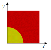
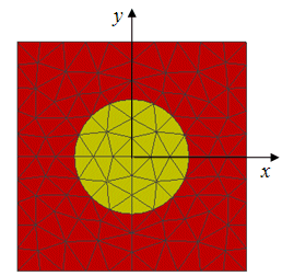
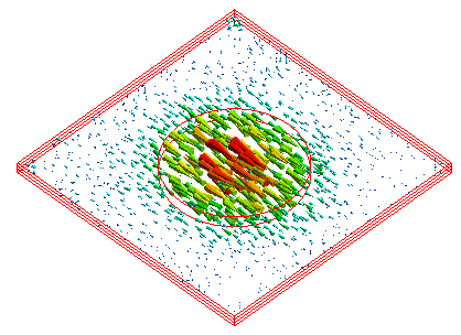
The diagram below shows meshing of the model in the 1st quadrant and the one copied at the faces of x=0 and y=0.
|
Model |
Mesh |
 |
 |
An Example of Resonant Analysis
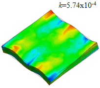
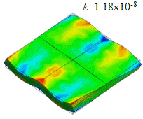
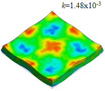
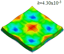
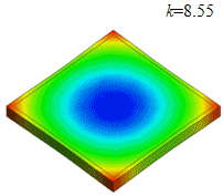
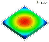
Resonant analysis is executed for a square piezoelectric device. Distribution of the deformation and the charge normal to the face of electric flux density are shown for three modes.
Mode 3 is the fundamental mode. Modes 1 and 2 are spurious.
For mode 1, the amount of electric charges in each of the four quadrants are equal with opposite properties.
The sum of charges is, therefore, zero, and the coupling coefficient k is essentially zero. With symmetric meshing, distributions of charges in the four quadrants are close to symmetric.
Compared with the ordinary meshing, the k value is reduced. It shows the effectiveness of the symmetric meshing.
|
|
Ordinary Meshes |
Symmetric Meshes |
|
1 |
 |
 |
|
2 |
 |
 |
|
3 |
 |
 |
K: coupling coefficient [%]
An Example of Harmonic Analysis
Let's solve example 9 of Piezoelectric Analysis (Thickness Shear Mode) with symmetric meshing.
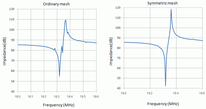
Impedance is calculated with ordinary meshing and symmetric meshing.
Calculation results of impedance are shown below. The left diagram is the result with ordinary meshing and the right diagram is the result with symmetric meshing. There are several spurious observed in the left diagram.
They are calculated with unbalanced charges due to the asymmetric meshes. This is a nonexistent mode in actuality.
The symmetric meshing solves this problem.
Operations
Click [Analysis Condition]  and go to the [Mesh] tab.
Click the Setup button of "Meshing control" to activate the dialog box. Select the planes of symmetry at Symmetric Mesh Copy.
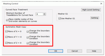
Select [Change the boundary condition] if you want to replace the boundary condition of the destination with that of the original.
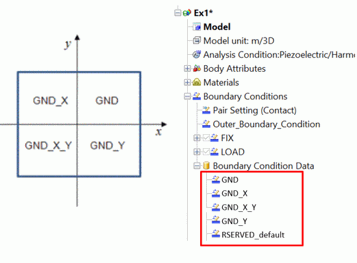
After meshing, new boundary condition will be created automatically with the name of "original" and "axis name".
In case of the example below, the original name is GND.
The newly created boundary condition can be edited at [Boundary condition] > [Boundary condition data] on the project tree.
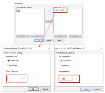
When copying a periodic boundary condition, a boundary pair is automatically set with a copy destination after meshing.
Since the phase difference is set to zero, if necessary, change it in the dialog box for the boundary pair setting.
Limiting Conditions
There are some limiting conditions:
1. Partial symmetric meshing is not possible. The whole model is subject to the symmetric meshing.
2. Symmetric faces are X-0, Y=0, and Z=0 only.
3. Symmetric meshing is not applicable to the adaptive mesh method.