


|
Home / Examples / Fluid Analysis [Bernoulli] / Example 5: Transient Analysis of Flow around Cylinder
Example 5: Transient Analysis of Flow around Cylinder
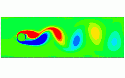
General
-
The flow around the cylinder is analyzed.
-
The flow velocity distribution, the fluid velocity vectors, the streamlines, the vorticity, and the force on the wall face are solved.
-
Unless specified in the list below, the default conditions are applied.
-
The above analysis can also be performed by using a circular sheet body as the model and applying [Automatic Fluid Creation].
The setting for the analysis is described at the end of this explanation.
-
Obtain this session's project file. (Right-click and choose 'Save link as')
The project has two analysis models.
・Analysis Model: Create fluid manually
・Analysis Model_Automatic Creation: Create fluid automatically -
Results will vary depending on Femtet version and the PC environment.
Analysis Space
|
Item |
Settings |
|
Analysis Space |
2D |
|
Model Unit |
mm |
Analysis Conditions
|
Item |
Tab |
Settings |
||||||||
|
Solver |
Solver Selection |
Fluid Analysis [Bernoulli] |
||||||||
|
Analysis Type |
Fluid Analysis |
Transient Analysis |
||||||||
|
Laminar Flow/Turbulent Flow |
Fluid Analysis |
Select Laminar flow |
||||||||
|
Flow Type |
Fluid Analysis |
Select External Flow. |
||||||||
|
Layer Mesh Setting |
Fluid Analysis |
Specify mesh height of 1st layer Height of 1st Layer Mesh: 0.5 [mm] |
||||||||
|
Timestep |
Transient Analysis |
Timestep: Specify
|
||||||||
|
Meshing Setup |
Mesh |
General Mesh Size: 3 [mm] |
Model
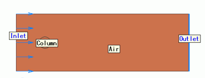
The model is a rectangular sheet body and the material is Air (000_Air). The boundary conditions of inlet and outlet are set on the left edge and the right edge, respectively.
The model is a circle sheet body and the material is iron (007_Fe).
The edges surrounding a circle is a boundary of solid and fluid. Solid wall is automatically set to them.
The outer boundary condition is automatically applied to the top and bottom edges where the boundary condition is not set.
The outer boundary condition will be [Slip Wall] automatically, because [External Flow] specified in the analysis condition comes with one-way forced convection
Body Attributes and Materials
|
Body Number/Type |
Body Attribute Name |
Material Name |
|
0/Solid |
Air |
000_Air(*) |
|
1/Solid |
Column |
007_Fe * |
* Available from the material DB
Boundary Condition
|
Boundary Condition Name/Topology |
Tab |
Boundary Condition Type |
Settings |
|
Inlet/Edge |
Fluid |
Inlet |
Forced Inflow |
|
Outlet/Face |
Fluid |
Outlet |
Natural Outflow |
The outer boundary condition will be [Slip Wall] automatically, because [External Flow] specified in the analysis condition comes with one-way forced convection
If Reynolds number exceeds 100, the time dependency of the turbulence occurs. It makes calculation difficult in the steady-state analysis.
The Reynolds number calculated with this model form, material property, and flow velocity is about 126.0. Use transient analysis instead.
Viscosity: μ=1.816e-5 [Pa s]
Density: ρ=1.144 [kg/m3]
Kinematic Viscosity: v=μ/ρ=1.816e-5/1.144=1.587e-5 [m2/s]
Flow Velocity: V=0.05 [m/s]
Diameter of Cylinder: D=0.04 [m]
Reynolds Number: Re = V*L/ν=0.05*0.04/1.587e-5 = 126.0
Results
The vectors of the flow velocity distribution around the cylinder at time 48 [s] and 50 [s] are shown below.
The vectors are adjusted to the same length in the graphics setup.
It is known that at a Reynolds number of 126, Karman vortices are shed from the alternating upper and lower sides at the back of the cylinder.
In the diagram below, a vortex appears on the upper side of the cylinder at 48 [s] and the lower side at 50 [s].
| 48 [s] | 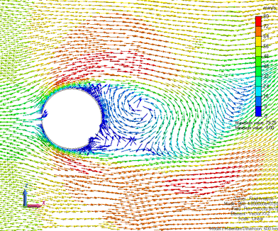 |
| 50 [s] | 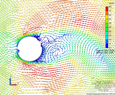 |
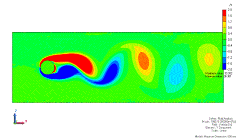
The figure below is the contour of Y component of the vorticity at 50 [s]. The color scale is minimum: -2 [/s] and maximum: 2 [/s].
The vortex strength in the Y direction is shown. The clockwise vortices are shown in the positive value, and the counter-clockwise vortices in the negative value.
You can observe the vortices are shed downstream from the cylinder.
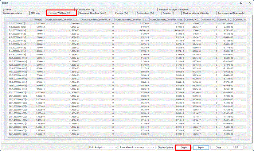
The force on the wall face is shown by the table.
[Column] shows the force which the cylinder receives from the fluid.
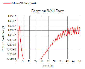
The result below shows only Column/X component (drag F: force in the flowing direction).
(Double click the graph to show the plot option. Deselect [Display Y-axis (primary axis)] except Column/X component. Change the color of column/X component to red.)
The range of the vertical axis scale is changed to between 9.5 x 10^-8 and 1.05 x 10^-7.
The drag force near time 50[s] fluctuates, centering around a central value of 1.02 x 10^-7 [N] , with a cycle of about 2 [s].
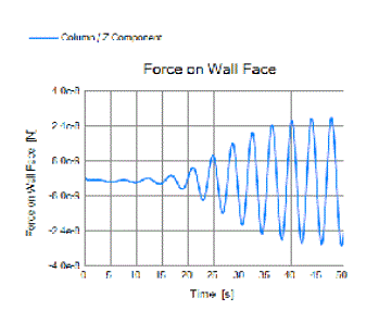
The result below shows only Column/Z component (lift: force in the direction perpendicular to the flow).
(Double click the graph to show the plot option. Deselect [Display Y-axis (primary axis)] except Column/Z component. Change the color of column/X component to blue.)
The range of the scale for the vertical axis is changed to -3 x 10^-8 ~3 x 10^-8.
You can see that the lift is fluctuating at a constant cycle of about 4 [s].
The coefficient of drag CD can be calculated from the drag F.
Thickness in Depth Direction: t = 1 [mm]
Cross Sectional Area: S = D * t = 0.04 * 0.001 = 4e-5 [m2]
Dynamic Pressure: Pk = 0.5 * ρ*V^2 = 0.5 * 1.144 * 0.05 * 0.05 = 1.430e-3 [Pa]
Coefficient of Drag CD = F / Pk / S = 1.02e-7 / 1.430e-3 /4e-5 = 1.78
Automatic Fluid Creation
For reference, the settings for analysis with [Automatic Fluid Creation] enabled are described below.
Analysis Conditions [Automatic Fluid Creation]
|
Item |
Tab |
Settings |
|
Solver |
Solver Selection |
Fluid Analysis [Bernoulli] |
|
Analysis Type |
Fluid Analysis |
Steady-state Analysis |
|
Laminar Flow/Turbulent Flow |
Fluid Analysis |
Select Laminar flow |
|
Flow Type |
Fluid Analysis |
Select External Flow. |
|
Flow Type Automatic Fluid Creation |
Fluid Analysis |
Deselect [Set the mesh size of the fluid domain automatically]. External Flow: Forced convection in the +X direction) External Flow Velocity: 0.05 m/s Scale Factor for Fluid Domain: 5 Scale Factor for Back Domain of Fluid: 10 |
|
Layer Mesh Setting |
Fluid Analysis |
Specify mesh height of 1st layer Height of 1st Layer Mesh: 0.5 [mm] |
|
Meshing Setup |
Mesh |
General Mesh Size: 3 [mm] |
Model [Automatic Fluid Creation]
The model is a circle sheet body and the material is iron (007_Fe).
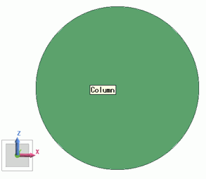
Body Attributes and Materials Setting [Automatic Fluid Creation]
|
Body Number/Type |
Body Attribute Name |
Material Name |
|
1/Solid |
Column |
007_Fe * |
Fluid material 000_Air * is set in the [Automatic Flow Creation] setting.
* Available from the material DB
Boundary Conditions [Automatic Fluid Creation]
Set no boundary condition. The external flow direction and velocity are set in the [Automatic Flow Creation] setting.