


|
Home / Examples / Fluid Analysis [Bernoulli] / Example 8: Swirling Flow in the Cylindrical Pipe
Example 8: Swirling Flow in the Cylindrical Pipe
General
-
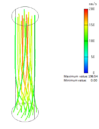
The swirling air flowing in the cylindrical pipe is simulated by the steady-state analysis.
-
The swirling flows are generated at the inlet of the pipe. The swirling component of the flow is gradually decreasing toward the outlet.
-
Unless specified in the list below, the default conditions are applied.
-
Obtain this session's project file. (Right-click and choose 'Save link as')
-
Results will vary depending on Femtet version and the PC environment.
Analysis Space
|
Item |
Settings |
|
Analysis Space |
3D |
|
Model Unit |
mm |
Analysis Conditions
|
Item |
Tab |
Settings |
|
Solver |
Solver Selection |
Fluid analysis [Bernoulli] |
|
Analysis Type |
Fluid Analysis |
Steady-state Analysis |
|
Meshing Setup |
Mesh |
General Mesh Size: 3 [mm] |
Model
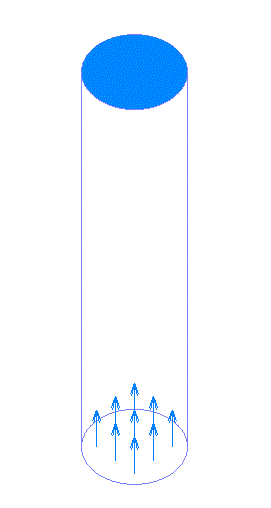
Creates a cylinder with body. As the boundary conditions, velocity vector and angular velocity are set to the bottom face and natural outflow to the top face.
Body Attributes and Materials
|
Body Number/Type |
Body Attribute Name |
Material Name |
|
0/Solid |
Air |
000_Air * |
* Available from the material DB
Boundary Condition
|
Boundary Condition Name/Topology |
Tab |
Boundary Condition Type |
Setting |
|
Inlet/Face |
Fluid |
Inlet |
Specify flow velocity Direction/Distribution Input (Specify cylindrical coordinates) Axial (inflow) Direction: 100 [mm/s] Angular Velocity: 360 [deg/ s] |
|
Outlet/Face |
Fluid |
Outlet |
Natural Outflow |
Results
As indicated by the velocity vectors and the streamlines,
the swirling component of the flow velocity are gradually decreasing toward the outlet.
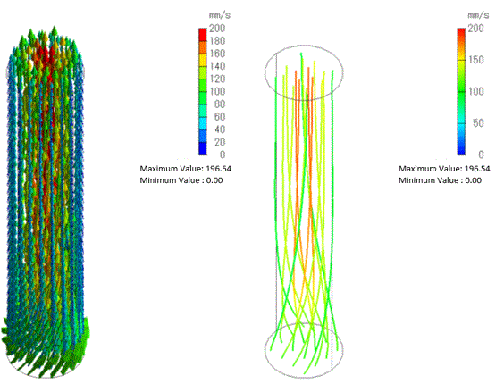
Fig. 1: Flow Velocity of the Swirling Flows (left: vector diagram, right: streamlines)