|
Home / Examples / Fluid Analysis [Bernoulli] / Example 9: Natural Inflow with Pressure Loss at Inlet
Example 9: Natural Inflow with Pressure Loss at Inlet
General
-
In this example, the loss coefficient is applied to the natural inflow boundary condition of Example 4.
-
Unless specified in the list below, the default conditions are applied.
-
Obtain this session's project file. (Right-click and choose 'Save link as')
-
Results will vary depending on Femtet version and the PC environment.
Analysis Space
|
Item |
Settings |
|
Analysis Space |
3D |
|
Model Unit |
mm |
Analysis Condition
|
Item |
Tab |
Settings |
|
Solver |
Solver Selection |
Fluid Analysis [Bernoulli] |
|
Analysis Type |
Fluid Analysis |
Steady-state Analysis |
|
Meshing Setup |
Mesh |
General Mesh Size: 6 [mm] |
Model
Body Attributes and Materials
|
Body Number/Type |
Body Attribute Name |
Material Name |
|
3/Solid |
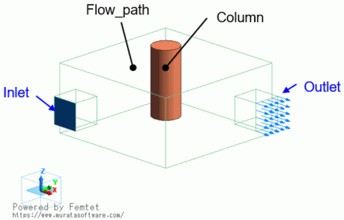
Flow_path |
000_Air(*) |
|
4/Solid |
Column |
007_Fe * |
* Available from the material DB
Boundary Condition
|
Boundary Condition Name/Topology |
Tab |
Boundary Condition Type |
Settings |
|||||||||
|
Inlet/Edge |
Fluid |
Inlet |
Natural Inflow Loss Coefficient: 4.5 |
|||||||||
|
Outlet/Face |
Fluid |
Outlet |
Forced Outflow PQ characteristics
|
Results
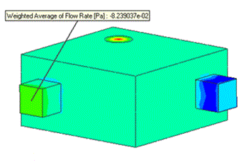
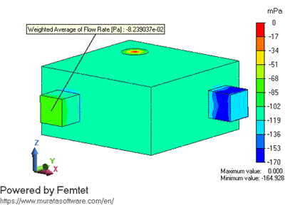
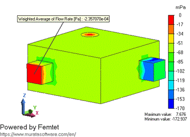
The figures below are the contour of the [Total Pressure] field.
The left figure shows the result using the pressure loss of 4.5. The right figure shows the result using the pressure loss of 0, that is without pressure loss.
The averaged total pressure without the loss coefficient at the inlet is almost 0 Pa.
With the loss coefficient being set, the averaged total pressure drops at the inlet.
| Loss Coefficient: 4.5 | Loss Coefficient: 0 |
 |
 |
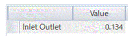
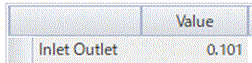
Below are the result tables of the pressure loss.
The pressure loss between the inlet and outlet becomes large if the loss is set at the inlet.
| Loss Coefficient: 4.5 | Loss Coefficient: 0 |
 |
 |
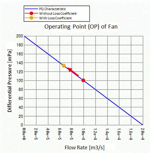
The operating points of the fan are compared between the models above.
The graph below shows that in the case that pressure loss has occurred at the inlet, the operating point of the fan shifts toward a lower flow rate due to the poorer efficiency of the fan.