


|
Home / Examples / Fluid Analysis [Bernoulli] / Example 22: Flow Separation Analysis with SST k-ω Turbulent Model
Example 22: Flow Separation Analysis with SST k-ω Turbulent Model
General
-
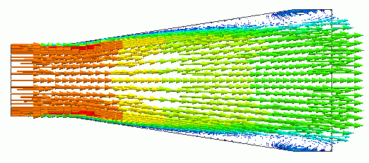
Flow separation near the wall face of a diffuser is analyzed with the SST k-ω model.
-
The flow velocity vectors indicate the flow separation.
-
Unless specified in the list below, the default conditions are applied.
-
Obtain this session's project file. (Right-click and choose 'Save link as')
-
Results will vary depending on Femtet version and the PC environment.
Analysis Space
|
Item |
Settings |
|
Analysis Space |
2D |
|
Model Unit |
mm |
Analysis Conditions
|
Item |
Settings |
|
Solver |
Fluid Analysis [Bernoulli] |
|
Analysis Types |
Transient Analysis |
|
Laminar Flow/Turbulent Flow |
Select Turbulent Flow Turbulent Model, SST k-ω Model |
|
Meshing Setup |
General Mesh Size: 1 [mm] Layer Mesh: Specify target y+ to 1. |
To calculate up to the turbulent boundary layer near the wall, specify the target y+ of layer mesh to 1.
A boundary layer is calculated with the Wolfshtein one-equation model in the k-ε model or with the k-ω model in the SST k-ω model.
Model
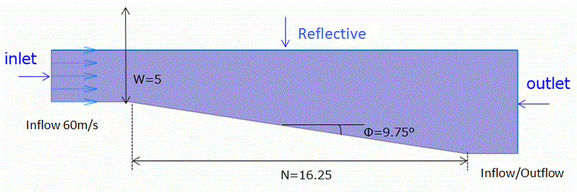
The model is a sheet body having a diffuser shape and the material is Air (000_Air). Inlet, Outlet, and Reflective boundary conditions are set on the left edge, right edge, and top edge, respectively.
On the bottom edge with no boundary condition, Solid Wall boundary condition is automatically set as an outer boundary condition.
The shape of the diffuser is defined as shown below.
Body Attribute and Material Setting
|
Body Number/Type |
Body Attribute Name |
Material Name |
|
0/Solid |
Flow_path |
000_Air * |
* Available from the material DB
Boundary Conditions
|
Boundary Condition Name/Topology |
Tab |
Boundary Condition Type |
Settings |
|
Inlet/Edge |
Fluid |
Inlet |
Forced Inflow |
|
Outlet/Face |
Fluid |
Inlet/Outlet |
Natural Inflow/Outflow |
|
Reflective/Face |
Symmetry/Continuity |
Symmetry |
Symmetry |
The Reynolds number calculated from this model form, material property, and flow velocity is about 10000. As the number is large, the turbulent flow is analyzed.
The project file of this example includes a turbulent model with the SST k-ω model. For comparison, it also includes a model with k-ε model and a model with Reynolds number (Re) of about 30000.
In the case of flow in a diffuser without laminar flow in the boundary layer, the occurrence of flow separation depends solely on the shape of the model, represented by N, W, and Φ.
The current shape of the diffuser, represented by N/W=3.25 and 2Φ=19.5°, is said to cause unsteady backflow from an experiment.
Results
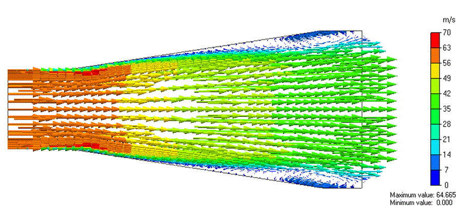
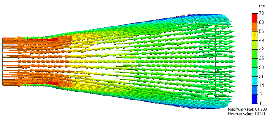
The distribution of the flow velocities is shown below.
・SST k-ω Model (Re is about 10000): 97 th step
・K-ε Model (Re is about 10000): 100 th step
The result from the SST k-ω model indicates the unsteady flow separation.
In contrast, the result with the k-εmodel indicates a steady flow along the wall surface without flow separation.
The analysis of the model with a Reynolds number of 30000, where the inflow velocity is changed, will give a result similar to the result from the model with a Reynolds number of 10000.
As shown above, the flow near the wall is analyzed accurately with the SST k-ω model. If your analysis particularly focuses on phenomena near the wall, you should use the SST k-ω model as the turbulent model.