


|
Home / Examples / Coupled Analysis / Electric-Fluid-Thermal Analysis [Coulomb/Bernoulli/Watt] / Example 1: Cooling of Strip Line by Natural Convection
Example 1: Cooling of Strip Line by Natural Convection
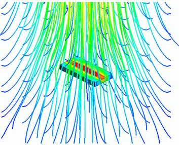
General
-
A strip line is heated by current flowing through it. Heat dissipation of the strip line by the natural convection is solved in the steady-state analysis.
-
The current density, the temperature distribution, and the flow velocity vectors are solved
-
Unless specified in the list below, the default conditions are applied.
-
The above analysis can be performed by modeling a substrate and an IC and applying [Automatic Fluid Creation].
The analysis can also be performed by creating a fluid manually. The setting for the analysis is described at the end of this explanation.
-
Obtain this session's project file. (Right-click and choose 'Save link as')
The project has two analysis models.
Ic_board: Fluid is created automatically.
Ic_board_with_air: Fluid is created manually.
-
Results will vary depending on Femtet version and the PC environment.
Analysis Space
|
Item |
Settings |
|
Analysis Space |
3D |
|
Model Unit |
mm |
Analysis Conditions
|
Item |
Settings |
|
Solver |
Electric Analysis [Coulomb] Fluid Analysis [Bernoulli] Thermal Analysis [Watt] |
|
Analysis Type |
Steady-state Analysis |
|
Laminar Flow/Turbulent Flow |
Select Turbulent Flow |
|
Flow Type |
Select External Flow. Select Take into account buoyancy (Natural Convection) |
|
Automatic Fluid Creation Setting |
External Flow: Natural convection in the +Z direction |
|
Layer Mesh Setting |
Parameters for Automatic Creation Expected Temperature Difference: 10 [deg] |
Model
Create a solid body for a substrate (Board) and a sheet body for a copper wire (LINE).
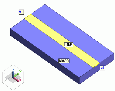
Setting of Body Attributes, Materials, and Mesh Sizes
|
Body Number/Type |
Body Attribute Name |
Thickness/Width |
Analysis Domain |
Material Name |
Mesh Size |
|
0/Solid |
Board |
- |
Solver: Deselect Electric Analysis (Coulomb) |
006_Glass_epoxy * |
General Mesh Size 1.0 |
|
1/Sheet |
LINE |
0.01mm |
- |
008_Copper (*) |
General Mesh Size 1.0 |
Fluid material 000_Air * is set in the [Automatic Flow Creation] setting.
* Available from the material DB
Boundary Condition
|
Boundary Condition Name/Topology |
Tab |
Boundary Condition Type |
Settings |
|
V0/Edge |
Electric |
Electric Wall |
Electric Potential Specified, Waveform: Constant, Electric Potential: 0 V |
|
V1/Edge |
Electric |
Electric Wall |
Electric Potential Specified, Waveform: Constant, Electric Potential: 10 mV |
Set no boundary condition to the thermal fluid. The external flow direction is set in the [Automatic Flow Creation] setting of the analysis condition dialog.
Set the inlet/outlet type of the outer boundary condition to natural inflow/outflow.
Since the temperature of the incoming fluid is the ambient temperature, the ambient temperature is applied In the [Ambient Setting] dialog box.
Results
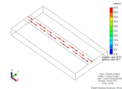
The vectors of the current density are shown below. The difference in electric potential causes a current to flow through the wiring.
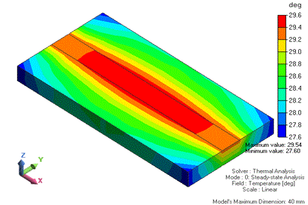
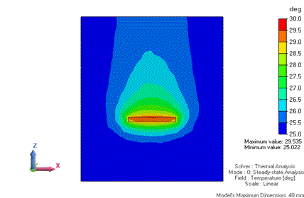
The temperature distribution is shown below.
For easy viewing of the temperature distributions of the substrate and the wiring, the air domain field is hidden by right-clicking the air body and selecting [Hide body field].
The wiring is heated by a flowing current.
The section at y=0 is shown below. The air body is shown as well.
Heat upward transmission from the strip line can be observed.
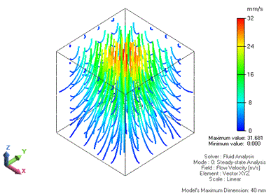
By switching the solver type from the thermal to fluid analysis, the flow velocity streamlines are shown as below.
The upward motion of air heated by the strip line can be observed.
Analysis Conditions [Manual Fluid Creation]
|
Item |
Settings |
|
Solver |
Electric Analysis [Coulomb] Fluid Analysis [Bernoulli] Thermal Analysis [Watt] |
|
Analysis Type |
Steady-state Analysis |
|
Laminar Flow/Turbulent Flow |
Select Turbulent Flow |
|
Flow Type |
Select External Flow. Select Take into account buoyancy (Natural Convection) |
|
Layer Mesh Setting |
Parameters for Automatic Creation Expected Temperature Difference: 10 [deg] |
Model [Manual Fluid Creation]
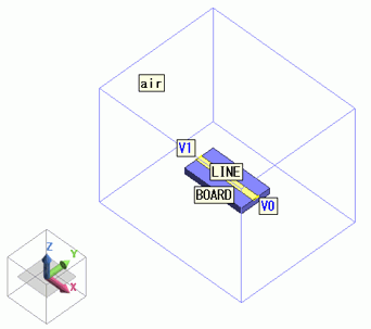
The model is a box solid body. The material is Air (000_Air).
Set Natural Inflow/Outflow for Inlet/Outlet with the outer boundary condition.
Inside the box, create a solid body of a substrate (Board) and a sheet body of a copper wiring (LINE).
Setting of Body Attributes, Materials, and Mesh Sizes [Manual Fluid Creation]
|
Body Number/Type |
Body Attribute Name |
Thickness/Width |
Analysis Domain |
Material Name |
Mesh Size |
|
0/Solid |
Board |
- |
Solver: Deselect Electric Analysis (Coulomb) |
006_Glass_epoxy * |
General Mesh Size 1.0 |
|
1/Sheet |
LINE |
0.01mm |
- |
008_Copper (*) |
General Mesh Size 1.0 |
|
2/Solid |
air |
- |
Solver: Deselect Electric Analysis (Coulomb) |
000_Air * |
2.5 |
* Available from the material DB
Boundary Condition [Manual Fluid Creation]
|
Boundary Condition Name/Topology |
Tab |
Boundary Condition Type |
Settings |
|
Outer Boundary Condition |
Fluid-Thermal |
Inlet/Outlet |
Natural Inflow/Outflow Inflow Temperature: Direct Entry( 25 [deg]) |
|
V0/Edge |
Electric |
Electric Wall |
Electric Potential Specified, Waveform: Constant, Electric Potential: 0 V |
|
V1/Edge |
Electric |
Electric Wall |
Electric Potential Specified, Waveform: Constant, Electric Potential: 10 mV |