|
Home / Examples / Coupled Analysis / Electric-Thermal Analysis [Coulomb/Watt] / Example 4: Heating of Conductive Strip (Transient Analysis with AC Voltage)
Example 4: Heating of Conductive Strip (Transient Analysis with AC Voltage)
General
-
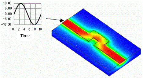
In this example, the electric potential setting in the Example 2 is modified to change the input.
-
The steady state after a long lapse time is calculated. The distributions of current on the conductive strip and temperature after heating are solved.
-
There are no changes in the other conditions.
-
Obtain this session's project file. (Right-click and choose 'Save link as')
-
Results will vary depending on Femtet version and the PC environment.
Analysis Conditions
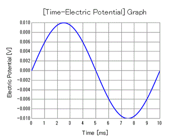
In this example, the sine wave of 100Hz is applied.
The timestep which is set in the transient analysis tab should be shorter than one eighth of the period time of 100 Hz (10[ms] / 8).
If [Automatic] is selected for the timestep and [Adjust referring to time-dependent condition] is selected in the [Detailed Automatic Timestep Setting] dialog box,
the timestep is set by dividing the periodic time automatically. The number of divisions is set to 12 by default.
The different tab settings from the example 2 are indicated in red as below.
|
Tab |
Setting Item |
Settings |
|
Transient analysis |
Timestep |
Automatic |
|
Restart |
Deselect |
|
|
Finish Time |
0.05 [s] |
|
|
Detailed Automatic Timestep Setting |
Select [Adjust referring to time-dependent condition] |
Boundary Conditions
The different settings from the example 2 are indicated in red as below.
All the other settings remain unchanged.
|
Boundary Condition Name/Topology |
Tab |
Boundary Condition Type |
Settings |
|
T_Wall/Face |
Thermal |
Adiabatic |
|
|
T0/Face |
Thermal |
Temperature |
25 [deg] |
|
V0/Face |
Electric |
Electric Wall |
Electric Potential Specified, Waveform: Constant, Electric Potential: 0.00 V |
|
V1/Face |
Electric |
Electric Wall |
Electric Potential Specified Waveform: Sine Wave Frequency: 100 Hz Electric Potential : Minimum -0.01 V : Maxmum +0.01 V |
|
Outer Boundary Condition * |
Thermal |
Heat Transfer/Convection |
Heat Transfer Voefficient: 10 [W/m2/deg] Ambient Temperature: 25 [deg] |
Click the Check Waveform button on the [Electric Wall] tab in the boundary condition setting dialog for the boundary condition, V1.
and the applied voltage will show up in graph form.
Results
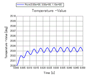
The temperature at (5.5, 3.5, 1.1) is shown below.