


|
Home / Examples / Electric Analysis [Coulomb] / Example 16: Anisotropic Conductor
Example 16: Anisotropic Conductor
General
-
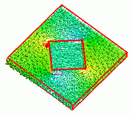
An anisotropic conductor is placed in an isotropic conductor.
-
By applying an electric potential difference, the electric field is generated.
The distributions of the electric field and the current density are solved.
-
Unless specified in the list below, the default conditions will be applied.
-
Obtain this session's project file. (Right-click and choose 'Save link as')
-
Results will vary depending on Femtet version and the PC environment.
Analysis Space
|
Item |
Settings |
|
Analysis Space |
3D |
|
Model Unit |
mm |
Analysis Conditions
Select [Static Analysis] as the electric potential is static.
Select a conductive material for analysis.
|
Item |
Settings |
|
Solver |
Electric Analysis [Coulomb] |
|
Analysis Type |
Static Analysis (Capacitance) |
|
Options |
N/A |
Model
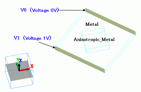
The anisotropic conductor has the highest conductivity in the x direction originally.
The highest-conductivity direction is changed when the anisotropic conductor is rotated during the modeling.
Body Attributes and Materials
|
Body Number/Type |
Body Attribute Name |
Material Name |
|
0/Solid |
Metal |
008_Cu * |
|
1/Solid |
Anisotropic_Metal |
Anisotropic_Cond |
* Available from the material DB
The conductivity of the anisotropic conductor is set as follows.
|
Material Name |
Electric Conductivity |
|||||||||
|
Anisotropic_Cond |
Anisotropy: Select [Anisotropic]. Set [Conductivity Matrix]*
X 107 [S/m] |
Boundary conditions
|
Boundary Condition Name/Topology |
Tab |
Boundary Condition Type |
Settings |
|
V0/Face |
Electric |
Electric Wall |
Electric Potential Specified 0 [V] |
|
V1/Face |
Electric |
Electric Wall |
Electric Potential Specified 1 [V] |
Results
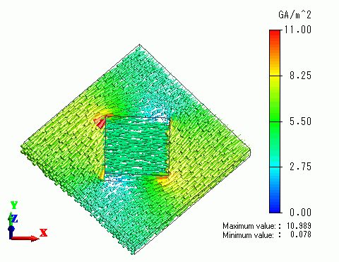
The current density vectors are shown below.
The electric field vectors are shown below.
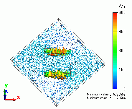
The directions of the current density and the electric field are different in the anisotropic conductor.
-
This example shows by applying the electric field in the direction of (1,1,0), the effect of the anisotropic conductor can be calculated.
Alternatively, by applying the electric field in the direction of (1,0,0) and setting the Euler angle of (0, 0, 45) to the body of anisotropic material
(on the [Direction] tab of [Body Attribute]), the same results can be obtained.