


|
Home / Examples / Electric Analysis [Coulomb] / Example 8: Plating Analysis (Hull Cell Test Bath)
Example 8: Plating Analysis (Hull Cell Test Bath)
General
-
The electric field in the electroplating solution in Hull Cell Test bath* is analyzed.
-
The overvoltage at anode and cathode is taken into account.
The current density in the bath and the distribution of plating thickness are solved. -
Unless specified in the list below, the default conditions will be applied.
-
Obtain this session's project file. (Right-click and choose 'Save link as')
-
Results will vary depending on Femtet version and the PC environment.
Analysis Space
|
Item |
Settings |
|
Analysis Space |
3D |
|
Model Unit |
mm |
Analysis Conditions
The material is conductor for the plating analysis.
Select the [Perform the plating analysis] option.
|
Item |
Settings |
|
Solver |
Electric Analysis [Coulomb] |
|
Analysis Type |
Static Analysis (Resistance) |
|
Options |
Select Perform the plating analysis |
Graphical Objects
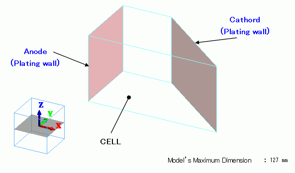
The plating bath (Hull cell bath) is a solid body. The material is the plating solution.
The electrodes are set with the plating wall boundary condition.
Body Attributes and Materials
The plating bath (Hull cell bath) is a solid body. The material is the plating solution.
|
Body Number/Type |
Body Attribute Name |
Material Name |
|
0/Solid |
Cell |
Plating Solution |
The body attribute of the plating solution is set as follows.
|
Body Attribute Name |
Plating Tab |
|
Cell |
Type of Plating Body: Plating solution |
The conductivity of the plating solution is set as follows.
|
Material Name |
Conductivity Tab |
|
Plating Solution |
Conductivity Type: Conductor Conductivity: 10 [S/m] |
Boundary Condition
The boundary conditions are set as follows.
|
Boundary Condition Name/Topology |
Tab |
Boundary Condition Type |
Settings |
||||||||||||||
|
Cathode/Face |
Electric |
Plating Wall |
Electrode Setting: Cathode
Overvoltage Type: Tafel's Law
|
||||||||||||||
|
Anode/Face |
Electric |
Plating Wall |
Electrode Setting: Anode
Overvoltage Type: Linear
Plating Condition: Current 1.0 [A] |
||||||||||||||
-
In this example, when the analysis is with the current of anode specified, Current is selected for the plating condition of the plating wall.
If the analysis is with the electric potential of anode specified, select Electric Potential.
Calculations of the electric potential-specified analysis is less than that of current-specified analysis, and the analysis time will be shorter.
Results
The current density vector is shown in Figure 1 below.
The current density distribution typical of the test bath is observed around the cathode.
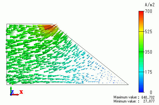
Fig. 1 Current density vector
By using the drawing feature of Femtet, show the plating thickness extracted on the cathode.
Fig. 2 shows the plating thickness along the cathode from the start point at the right bottom up to the right top in Fig. 1.
Plating thickness is distributed according to the current density.
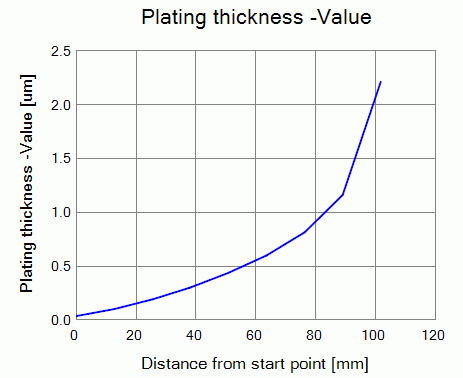
Fig. 2 Distribution of the plating thickness
-
Refer to Field Graph for the detail of graph drawing.
(*) "Hull cell" is a product of Yamamoto-MS Co., Ltd.