


|
Home / Examples / Stress Analysis [Galileo] / Example 23: Deformation due to Centrifugal Force
Example 23: Deformation due to Centrifugal Force
General
-
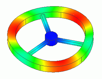
The deformation due to the centrifugal force is analyzed.
-
The deformation, the displacement distribution, and the stress distribution are solved.
-
Unless specified in the list below, the default conditions will be applied.
-
Obtain this session's project file. (Right-click and choose 'Save link as')
-
Results will vary depending on Femtet version and the PC environment.
Analysis Space
|
Item |
Settings |
|
Analysis Space |
3D |
|
Model Unit |
mm |
Analysis Conditions
Select [Angular Velocity] at Options.
The analysis type is [Static Analysis].
|
Item |
Settings |
|
Solver |
Stress Analysis [Galileo] |
|
Analysis Type |
Static Analysis |
|
Options |
Select [Angular Velocity]. |
The Angular Velocity tab is set as shown below.
It is equal to 100 rotations a second.
|
Tab |
Setting Item |
Settings |
|
Angular velocity |
Z component |
360X102 [deg/s] |
Model
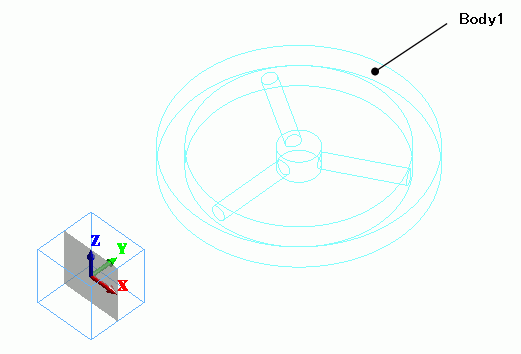
If the angular velocity is opted, the rotational axis is Z axis. Therefore the model is created to be symmetric with reference to Z axis.
Cylindrical solid bodies are created and they are modified with boolean operations.
Body Attributes and Materials
|
Body Number/Type |
Body Attribute Name |
Material Name |
|
7/Solid |
Body1 |
008_Cu * |
* Available from the material DB
Boundary Conditions
N/A
Results
The Z-direction displacement is shown below by contour. The contour diagram shows the magnitude of displacement.
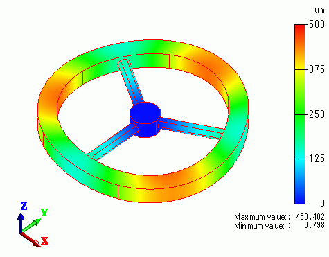
The non-supported portions of outer wheel deforms outwards.
The vectors of the stress are shown below.
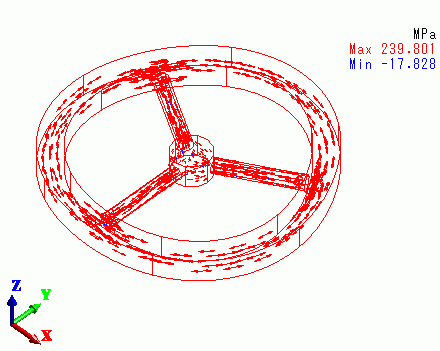
The tensile stress is generated throughout the model, concentratedly generated at the supporting portions.