


|
Home / Examples / Stress Analysis [Galileo] / Example 28: Contact Analysis with Large Deformation
Example 28: Contact Analysis with Large Deformation
General
-
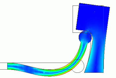
A round-head stick in contact with a concave face. The stick is subjected to the large deformation. The deformation is analyzed.
-
Unless specified in the list below, the default conditions will be applied.
-
Obtain this session's project file. (Right-click and choose 'Save link as')
-
Results will vary depending on Femtet version and the PC environment.
Analysis Space
|
Item |
Settings |
|
Analysis Space |
2D |
|
Model Unit |
mm |
Analysis Conditions
[Large Displacement] is selected for the [Large Deformation].
[Large Displacement] is more suitable than [Large Strain] for this model.
|
Item |
Settings |
|
Solver |
Stress analysis [Galileo] |
|
Analysis Type |
Static Analysis |
|
Large deformation |
Select [Large Displacement] |
The nonlinear analysis is set up on the Step/Thermal Load tab as follows.
Number of Substeps is set to 40, which is larger than the default setting of 20 because the stick exhibits a large deformation and the contact point changes drastically.
As Save results of substeps is selected, states at intermediate substeps through the final step will be saved.
|
Tab |
Setting Item |
Settings |
|
Step/Thermal Load |
Step/Reached Temperature Setting |
Substeps of Step 1 : 40 |
|
Options for the Nonlinear Analysis |
Save the results of substeps : Select |
Model
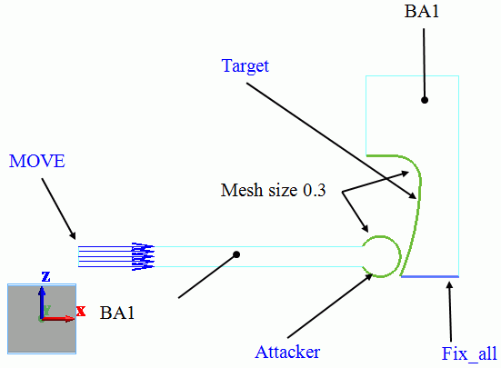
This model consists of two bodies: BA1 and BA2. They have the same body attributes and material properties.
The mesh size of contact surfaces is set to 0.3 [mm], which is smaller than general mesh size of 0.9 [mm].
Body Attributes and Materials
|
Body Number/Type |
Body Attribute Name |
Material Name |
|
2/Sheet |
BA1 |
M1 |
|
7/Sheet |
BA1 |
M1 |
The material properties are set up as follows:
|
Material Name |
Tab |
Properties |
|
M1 |
Elasticity |
Young's Modulus: 1×10⁹ [Pa] Poisson's Ratio: 0.3 |
Boundary Conditions
On the left end of the stick, the forced displacement of 4.5 [mm] is applied in the right direction (positive x direction).
The bottom of the target with a concave face is fixed completely.
|
Boundary Condition Name/Topology |
Tab |
Boundary Condition Type |
Settings |
|
Fix_x/Edge |
Mechanical |
Displacement |
Select the XZ component. UX=0, UZ=0 |
|
MOVE/Edge |
Mechanical |
Displacement |
Select the XZ component. UX = 4.5 x 10⁻³ [m] UZ = 0.0 x 10⁻³ [m] |
|
Contactor/Edge |
Mechanical |
Contact Surface |
Select [Contactor surface]. |
|
Target/Edge |
Mechanical |
Contact Surface |
Select [Contactee surface]. |
The contactor and contactee surfaces are designated as a contact pair in the [Boundary Pair] dialog. In contact analyses, the contact surfaces must be designated as a boundary pair.
Results
The displacement and the stress distribution at the step 0.2 (corresponding to the displacement of 0.9 [mm] in X direction of MOVE) are shown below.
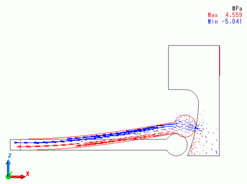
The round head of the stick slides on the concave surface of the target.
The displacement and the stress distribution at the step 0.4 (corresponding to the displacement of 1.8 [mm] in X direction of MOVE) are shown below.
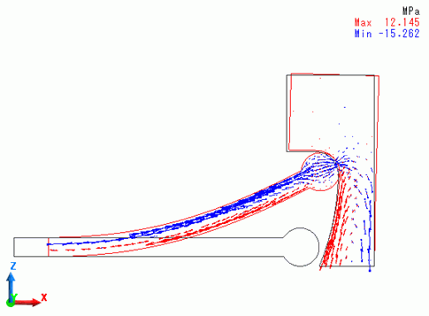
The head reaches the upper end of the concave surface.
The displacement and the stress distribution at the step 0.7 (corresponding to the displacement of 3.15 [mm] in X direction of MOVE) are shown below.
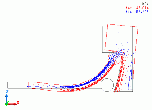
The head starts to rotate. The stick exhibits the large deformation and the target deforms as well.
The displacement and the stress distribution at the step 1 (corresponding to the displacement of 4.5 [mm] in X direction of MOVE) are shown below.
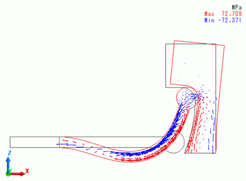
The stick and target body deformed further. Compared with the state at step 0.4, the contact point moved further upward.
On the [Show Results] tab, go to 
and click [Create Animation] . The animation file (.avi) will be created using the displayed results.
The animation gives you an intuitive visual understanding of the large deformation.