


|
Home / Examples / Stress Analysis [Galileo] / Example 48: Buckling Analysis
Example 48: Buckling Analysis
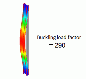
General
-
The buckling analysis is performed on an H-shaped steel structure.
-
The structure's buckling load factor and the buckling modes are solved.
-
Unless specified in the list below, the default conditions will be applied.
-
Obtain this session's project file. (Right-click and choose 'Save link as')
-
Results will vary depending on Femtet version and the PC environment.
Analysis Space
|
Item |
Settings |
|
Analysis Space |
3D |
|
Model Unit |
mm |
Analysis Conditions
The analysis type is buckling analysis
|
Item |
Settings |
|
Solver |
Stress Analysis [Galileo] |
|
Analysis Type |
Buckling Analysis |
Model
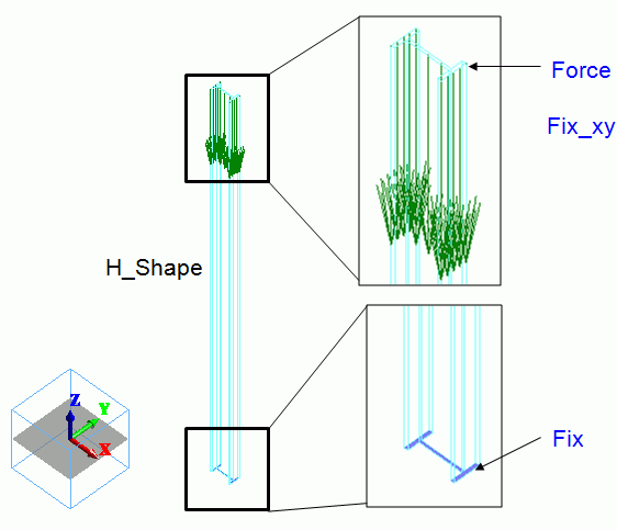
An H-shaped sheet body is created on XY plane. It is extruded to form an H-shape pillar.
The bottom face is fixed. The top face is loaded downward and fixed in X and Y directions. Uniform displacement is set on it.*
* The uniform displacement prevents the rotational displacement.
Body Attributes and Materials
|
Body Number/Type |
Body Attribute Name |
Material Name |
|
0/Solid |
H_shape |
104_Stainless_steel * |
* Available from the material DB
Boundary Conditions
|
Boundary Condition Name/Topology |
Tab |
Boundary Condition Type |
Settings |
|
Fix/Face |
Mechanical |
Displacement |
Select all X/Y/Z components. UX=0, UY=0, UZ=0 |
|
Force/Face |
Mechanical |
Load |
Select [Set the total load]. X=0.0, Y=0.0, Z=-1000 |
|
Fix_xy/Face |
Mechanical |
Displacement |
Select X and Y components. UX=0, UY=0 Select [Uniform Displacement] |
* As the boundary conditions (Force and Fix_xy) need to be set on the same face, select Add in the second boundary condition setting.
Results
The following will be output on the Output Window or the log file.
|
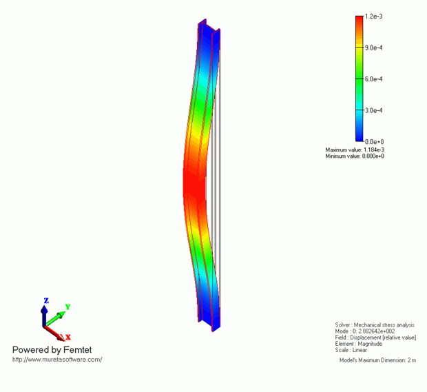
<<Buckling Analysis>> Buckling load factor Mode[ 0] = 2.88264161e+002
Multiply the original load with the buckling load factor to acquire the buckling load. Field values such as displacement, strain, stress, etc acquired by the buckling analysis are all relative. |
In this model, the buckling load factor is 288.
The applied load on “Force" is 1000 [N]. Therefore, the buckling load is calculated to be 288 [KN].
The Z-direction displacement is shown below by contour. The contour diagram shows the magnitude of displacement. The displacement is relative.
Compare with Theoretical Values
The buckling load for a H-shaped pillar is given by the following formula.
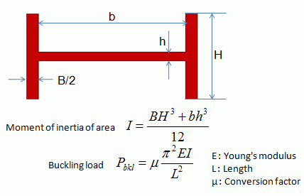
In this case,
B/2 = 7e-3 [m]
b = 86e-3 [m]
H = 50e-3 [m]
h = 5e-3 [m]
E = 2e11 [Pa]
L = 2.0 [m]
μ=4, which means that there is no horizontal or rotational displacement for either end.
These values yield I = 14.7e-8 [m4] and Pbkl = 290 [KN]
The result of Femtet matches this Pbkl quite well.