|
Home / Examples / Stress Analysis [Galileo] / Example 74: Roll-Up Model with Shell Elements
Example 74: Roll-Up Model with Shell Elements
General
-
Shell elements allow you to analyze models with large aspect ratios with fewer meshes
-
Unless specified in the list below, the default conditions will be applied.
-
Obtain this session's project file. (Right-click and choose 'Save link as')
-
Results will vary depending on Femtet version and the PC environment.
Analysis Conditions
To set the rotational degree of freedom of shell elements, select [Constrain the freedom of shells] in the options of the stress analysis.
Even 1st-order elements can achieve high analysis accuracy for shell elements. Select [1st-Order Element] as the element order.
|
Item |
Settings |
|
Solver |
Stress Analysis [Galileo] |
|
Analysis Space |
3D |
|
Analysis Type |
Static Analysis |
|
Unit |
m |
|
Options |
Select [Constrain the freedom of shells] Large Displacement
|
|
Mesh - Element Type |
Hexahedral-Free/Sweep Mesh |
|
Mesh - Element Order |
1st-Order Element |
Model
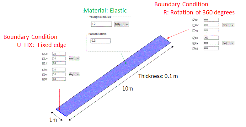
To model a thin beam with sheet elements, create a sheet body, of which body attribute name is Beam, with a size of 10x1 mm, and specify 0.1 m as the thickness of sheet body.
Body Attribute and Material Setting
|
Body Number/Type |
Body Attribute Name |
Material Name |
|
0/Sheet |
Beam |
Mat1 * |
* Young's modulus is 12 MPa and Poisson's ration is 0.3.
Boundary Conditions
|
Boundary Condition Name/Topology |
Tab |
Boundary Condition Type |
Settings |
|
U_FIX/Edge |
Mechanical |
Displacement |
Select all UX/UY/UZ and RX/RY/RZ components. |
|
R/Edge |
Mechanical |
Displacement |
Select the UX component UX=0
Select all RX/RY/RZ components. RX=360, RY=RZ=0.0 |
Results
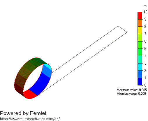
The deformation diagram (actual scale) is shown below.
This model is the Roll-Up model often used in benchmarks for geometric nonlinearity analysis where large displacements of shell elements are taken into account.
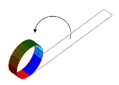
Since the rotational degree of freedom at the tip of the beam is set to 360 degrees, the fixed end and the free end align, resulting in nearly circular deformation as observed in the diagram.