|
Home / Examples / Stress Analysis [Galileo] / Example 57: Hydrostatic Pressure
Example 57: Hydrostatic Pressure
General
-
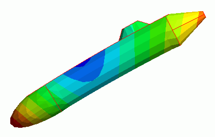
Deformation by the hydrostatic pressure is simulated.
-
The deformation, the displacement distribution, and the stress distribution are solved.
-
Unless specified in the list below, the default conditions will be applied.
-
Obtain this session's project file. (Right-click and choose 'Save link as')
-
Results will vary depending on Femtet version and the PC environment.
Analysis Space
|
Item |
Settings |
|
Analysis Space |
3D |
|
Model Unit |
m |
Analysis Conditions
|
Item |
Settings |
|
Solver |
Stress Analysis [Galileo] |
|
Analysis Type |
Static Analysis |
|
Options |
N/A |
As the buoyant force causes acceleration in +Z direction, setting on the High-level setting tab is done as follows.
|
Tab |
Setting Item |
Setting |
|
High-level setting |
Setting of Stress Analysis and Piezoelectric Analysis |
Select [Perform static analysis in the acceleration environment with inertial force taken into account]. |
Graphical Objects
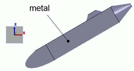
The model is like a 115-meter submarine sailing down toward the sea bottom.
Body Attributes and Materials
|
Body Number/Type |
Body Attribute Name |
Material Name |
|
0/Solid |
metal |
007_Fe * |
* Available from the material DB
Boundary Conditions
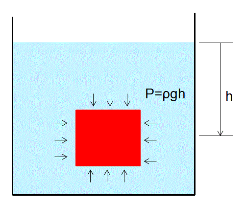
The hydrostatic pressure on the whole surface of the model is proportional to the depth. The pressure is expressed in the following equation.
P=ρgh
where ρ is density [kg/m3], g is gravitational acceleration [m/s2], and h is depth [m]. For the water, it is expressed as follows.
P=9800h [Pa]
-
In this model, the boundary condition is only pressure. The displacement is not constrained.
Generally, the simulation cannot be performed without constraining the displacement. Femtet is, however, capable of doing so without constrained displacement.
For the Pressure, set [Distribution Data] of the [Edit Boundary Condition].
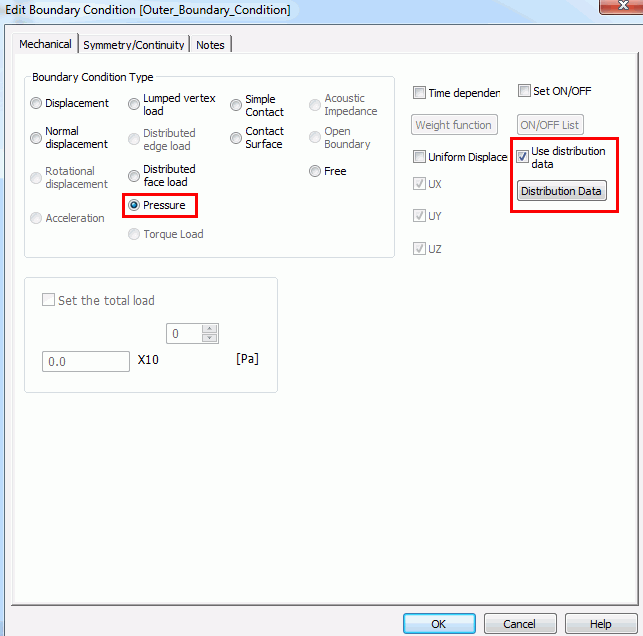
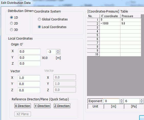
In the [Edit Distribution Data] dialog box, select 1D and set Z direction in the Local Coordinates. In the [Coordinates-Pressure],
specify the pressures at two end points in the area where the whole body is included. Linear interpolation is applied between the points.
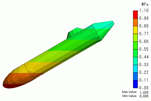
After meshing, select [Distributed Pressure] in the Mesh display to show the pressure distribution of the surface.
Results
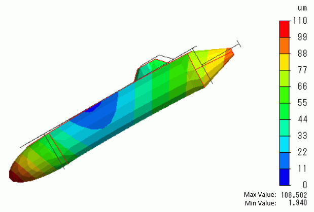
The Z-direction displacement is shown below by contour. The contour diagram shows the magnitude of displacement.
The whole body shrinks under the pressure. The deformation is irregular due to its asymmetric shapes of upper and bottom sides of the model.
If the model is symmetric, the shrinkage will be uniform over the whole body.
The displacement is minute as the deformation is only 100um against the body length of 115 meters.