


|
Home / Examples / Stress Analysis [Galileo] / Example 68: Analysis with Overlapping Meshes
Example 68: Analysis with Overlapping Meshes
General
-
A shaft is inserted into a ring. The outer diameter of the shaft is slightly larger than the inner diameter of the ring.
-
In this example, overlapping meshes are used for the ring hole and the shaft. A similar analysis is performed in Example 42 where the initial strain is used.
Unlike Example 42, it is not required to calculate the initial strain manually in advance in this example. Also, the analysis can be performed even if the initial strain is not obtained.
-
The distributions of displacement and stress are solved.
-
Unless specified in the list below, the default conditions are applied.
-
Obtain this session's project file. (Right-click and choose 'Save link as')
-
Results will vary depending on Femtet version and the PC environment.
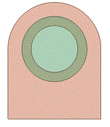
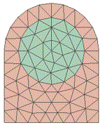
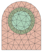
To create the overlapping meshes, the ring hole and the shaft must be meshed in the different meshing spaces. If meshing in the same meshing space, an overlapping area is absorbed in either one of the bodies and
the overlapping meshes will not be created.
|
Overlapping Bodies |
Same Meshing Space (meshes do not overlap) |
Different Meshing Spaces (meshes overlap) |
|
|
|
|
Analysis Space
|
Item |
Settings |
|
Analysis Space |
3D |
|
Unit |
mm |
Analysis Conditions
|
Item |
Settings |
|
Solver |
Stress Analysis [Galileo] |
|
Analysis Type |
Static Analysis |
|
Analysis Options |
None |
Model
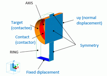
For a stable contact analysis, the calculation is performed on the half of the model in X direction, and a symmetric boundary condition is applied to the plane of symmetry.
Body Attributes and Materials
|
Body Number/Type |
Body Attribute Name |
Material Name |
|
0/Solid |
RING |
001_Al * |
|
1/Solid |
AXIS |
001_Al * |
* Available from the material DB
|
Body Attribute Name |
Tab |
Space Number |
|
RING |
Analysis Domain |
1 |
|
AXIS |
Analysis Domain |
2 |
Boundary Condition
The boundary conditions are set as follows.
|
Boundary Condition Name/Topology |
Tab |
Boundary Condition Type |
Setting |
|
Target/Face |
Mechanical |
Contact Surface |
Select [Contactor Surface]. |
|
Contact/Face |
Mechanical |
Contact Surface |
Select [Contactee Surface]. |
|
Fix/Face |
Mechanical |
Displacement |
Select all of X/Y/Z components. UX=0, UY=0, UZ=0 |
|
Symmetry/Face |
Symmetry/Continuity |
Plane of Symmetry |
Select [Reflective] on the Symmetry/Continuity Tab |
|
uy |
Mechanical |
Normal Displacement |
Displacement is zero |
Results
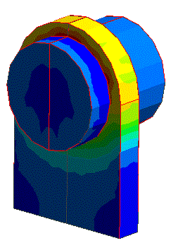
The contacting face pressure is shown below. The vectors show the pressure and directions on the contacting face. The unit is [Pa].
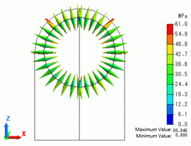
The model dimension, the fitting differential, and the material are the same as in Example 42. Similar pressure is generated.