|
Home / Examples / Stress Analysis [Galileo] / Example 72 Bending Analysis with Shell Elements
Example 72 Bending Analysis with Shell Elements
General
-
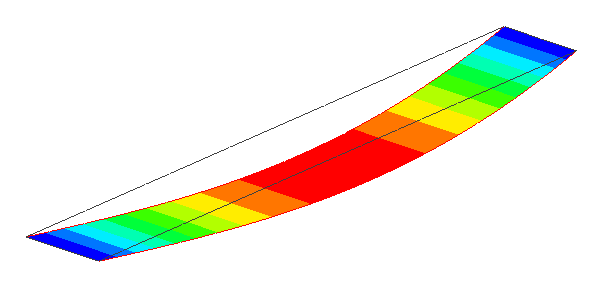
Using shell elements, a model with a large aspect ratio can be analyzed with fewer meshes.
-
Unless specified in the list below, the default conditions will be applied.
-
Obtain this session's project file. (Right-click and choose 'Save link as')
-
Results will vary depending on Femtet version and the PC environment.
Analysis Conditions
|
Item |
Settings |
|
Solver |
Stress Analysis [Galileo] |
|
Analysis Space |
3D |
|
Analysis Type |
Static Analysis |
|
Unit |
mm |
|
Analysis Options |
Select [Constrain the freedom of shells]
|
Model
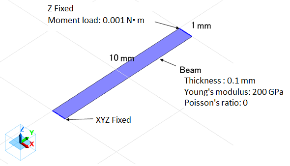
To model a thin beam with sheet elements, create a sheet body, of which body attribute name is Beam, with a size of 10x1 mm, and specify 0.1 mm as the thickness of sheet body.
Body Attributes and Materials Setting
|
Body Number/Type |
Body Attribute Name |
Material Name |
|
0/Sheet |
Beam |
Material Property_001 * |
* To compare the results with theoretical calculations, a special case is considered in which Young's modulus and Poisson's ratio of the material properties are set to 200 GPa and 0, respectively.
Boundary Condition
|
Boundary Condition Name/Topology |
Tab |
Boundary Condition Type |
Settings |
|
Fix/Edge |
Mechanical |
Displacement |
Select all UX/UY/UZ components. UX=0, UY=0, UZ=0
Unselect all RX/RY/RZ components. |
|
Fix_z/Edge |
Mechanical |
Displacement |
Select the UZ component UZ=0
Unselect other boundaries |
|
Tributary_Moment/Edge |
Mechanical |
Distributed Face Load |
Select [Set the total load]. MX=0.001 |
Results
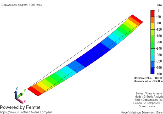
Below is the displacement diagram with contours of Z displacement.
Comparison with Theoretical Calculation
Compare the results with the theoretical calculation of the bending moment load problem below.
Below is shown the theoretical model replicating the analysis model.
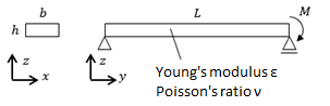
The following table lists the values of the model variables for the theoretical solution.
The values are given to match the model dimensions, boundary conditions, body attributes, and material properties of the project file.
| Item | Symbol | Value | Unit |
| Moment Load | M | 0.001 | N·m |
| Young's Modulus | E | 2e+11 | Pa |
| Poisson's Ratio | ν | 0 | - |
| Length of beam | L | 0.01 | m |
| Width of beam | b | 0.001 | m |
| Thickness of beam | h | 0.0001 | m |
Below are formulas that give the second moment of a section in the bending load applied direction
and the bending displacement, z, at the position, y.
Noted that gravity is not taken into account.

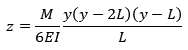
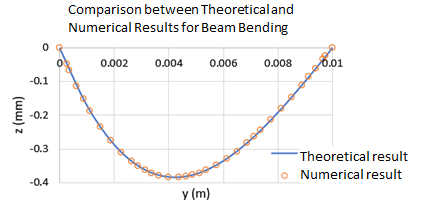
The result of the comparison between the calculated result from the equations above and the analysis result of Example 72 is shown below.