


|
Home / Examples / Magnetic Analysis (Gauss, Static Analysis/Harmonic analysis) / Example 27: Current Induced in Wire-Wound Inductor
Example 27: Current Induced in Wire-Wound Inductor
General
-
The current induced in a wire-wound Inductor is analyzed.
-
The current distribution and the resistance are solved.
-
This will be an axisymmetric analysis.
-
Unless specified in the list below, the default conditions will be applied.
-
Obtain this session's project file. (Right-click and choose 'Save link as')
-
Results will vary depending on Femtet version and the PC environment.
Analysis Space
|
Item |
Settings |
|
Analysis Space |
Axisymmetric |
|
Model Unit |
mm |
Analysis Conditions
|
Item |
Settings |
|
Solver |
Magnetic Analysis [Gauss] |
|
Analysis Type |
Harmonic Analysis |
|
Options |
Deselect Inductance Calculation. |
The frequency is swept from 1MHz to 10MHz in 1MHz interval.
|
Tab |
Setting Item |
Settings |
|
Harmonic analysis |
Frequency |
Minimum: 1×10⁶ [Hz] Maximum: 10x106 [Hz] |
|
Sweep Type |
Linear Step by Number of Divisions: Number of Divisions 9 |
Model
The axisymmetric analysis is performed. For a model which is symmetric around Z axis,
the simulation is done for the X-Z section only. It is virtually 2D analysis.
The calculation is much faster than 3D analysis.
The model in this example is especially complex with many wound wires.
It is practically impossible to analyze such a complex model in 3D. The axisymmetric analysis is necessary.
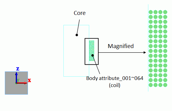
A core is placed in center, and the coil is wound on the core.
The coil is formed by 16 turns in Z direction and 4 layers in X direction. It is 64 turns in total.
The right half section of the model is analyzed.
Body Attributes and Materials
|
Body Number/Type |
Body Attribute Name |
Material Name |
Mesh Size |
|
0-63/Sheet 65/Sheet |
Body_Attribute_001 to 064 CORE |
008_Cu * CORE |
0.01
|
* Available from the material DB
Set the current as follows.
|
Body Attribute Name |
Tab |
Settings |
|
Body_Attribute_001 to 064 |
Current |
Waveform: AC Current: 1 [A] Turns: 1 [Turns] Direction: +Y direction |
Boundary Conditions
No setting.
Results
The following are solved.
1) Magnetic flux lines
2) Current density distribution
3) Frequency response of the inductor's resistance
4) Inductance
1) Magnetic flux lines
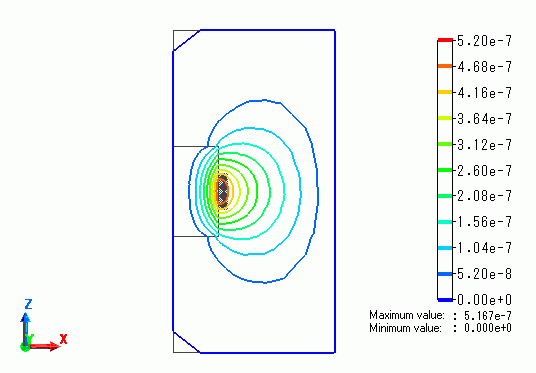
The figure below shows the magnetic flux lines at 10MHz.
2) Current density distribution
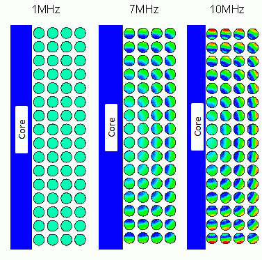
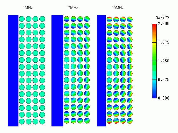
The figure below shows the current distribution. The current flows uniformly at 1MHz. At higher frequencies, the current flows unevenly especially in the outer windings.
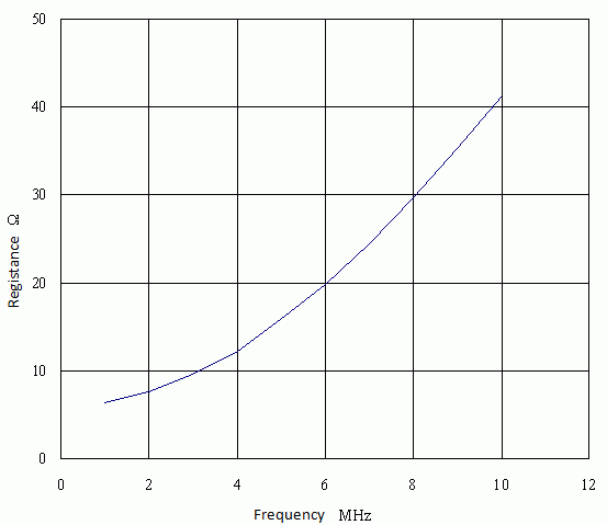
3) Frequency response of the inductor's resistance
The chart below is the inductor's resistance. It is higher at higher frequency.
-
How to calculate the resistance
As the analysis results, the loss P [W] is displayed on the output window or on the table.
P = 1/2*R*I*I and I = 1 [A] (peak value). Therefore, R is given as R = 2*P.
4) How to calculate the total inductance of 64 coils
Femtet can calculate the inductance of each of the 64 coils but cannot calculate the total inductance of all the coils.
Instead, here, it is calculated manually using the output values of magnetic energy.
The magnetic energy (Em) is expressed as 1/2*L*I*I, where L is the inductance and I is the current.
Using a current of 1 A for the calculation, the magnetic energy is given as 1.563e-5 [J] in the calculation table.
Then, the manual calculation yields an inductance of 31.26 [uH].