|
Home / Examples / Magnetic Analysis (Gauss, Static Analysis/Harmonic analysis) / Example 32: Magnetic Field of Three-Phase AC
Example 32: Magnetic Field of 3-Phase AC
General
-
Three-phase AC current flows in three conductors.
-
The magnetic field vectors and the conductors' inductance and impedances are solved.
-
Unless specified in the list below, the default conditions will be applied.
-
Obtain this session's project file. (Right-click and choose 'Save link as')
-
Results will vary depending on Femtet version and the PC environment.
Analysis Space
|
Item |
Settings |
|
Analysis Space |
3D |
|
Model Unit |
mm |
Analysis Conditions
|
Item |
Settings |
|
Solver |
Magnetic Analysis [Gauss] |
|
Analysis Type |
Harmonic Analysis |
|
Options |
N/A |
The frequency of the current is set to 10 [kHz].
|
Tab |
Setting Item |
Settings |
|
Mesh Tab |
Frequency-Dependent Meshing |
Reference Frequency: 10x103 [Hz] |
|
Harmonic analysis |
Sweep Type |
Single Frequency |
|
Frequency |
10×103 [Hz] |
Set the Mesh Tab as follows.
|
Tab |
Setting Item |
Settings |
|
Mesh Tab |
Meshing Setup |
Automatically set the general mesh size: Deselect General Mesh Size: 2 [mm] |
Model
Conductors (Coil_u, Coil_v and Coil_w) are defined.
U, V, and W are phased at 0, -120, and +120 [deg] respectively.
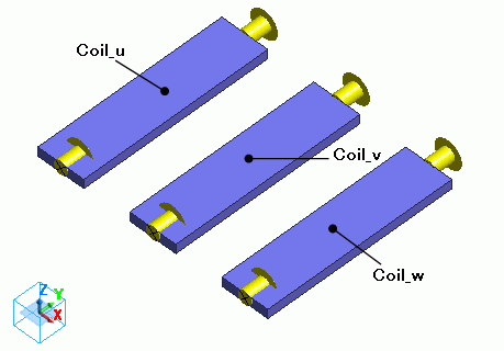
Body Attributes and Materials
|
Body Number/Type |
Body Attribute Name |
Material Name |
|
1/Solid |
Coil_u |
008_Cu * |
|
2/Solid |
Coil_v |
008_Cu * |
|
3/Solid |
Coil_w |
008_Cu * |
* Available from the material DB
Body attribute is set up as follows to apply currents to each of the three coils.
U, V, and W are phased at 0, -120, and +120 [deg] respectively.
|
Body Attribute Name |
Tab |
Settings |
|
Coil_u |
Current |
Waveform: AC Current: 1 [A] Phase: 0 [deg] Turns: 1 [Turns] Direction: Specify Inflow/Outflow faces Select Inflow face and Outflow face. |
|
Coil_v |
Current |
Waveform: AC Current: 1 [A] Phase: -120 [deg] Turns: 1 [Turns] Direction: Specify Inflow/Outflow faces Select Inflow face and Outflow face. |
|
Coil_w |
Current |
Waveform: AC Current: 1 [A] Phase: 120 [deg] Turns: 1 [Turns] Direction: Specify Inflow/Outflow faces Select Inflow face and Outflow face. |
Boundary Conditions
No setting.
Results
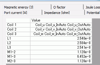
To see the results of inductance and impedance calculation, go to the [Results] tab
and click [Show Numerical Summary Table]  .
.
The inductance is as follows.
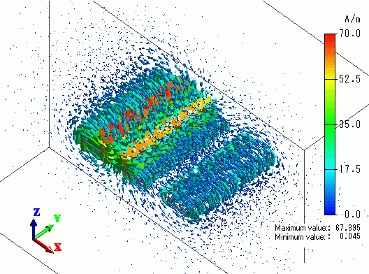
Shown below is the vectors of the magnetic field at Phase=0 [deg].
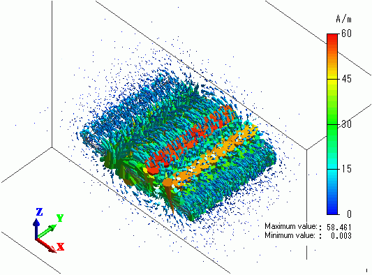
Shown below is the vectors of the magnetic field at Phase=120 [deg].
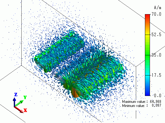
Shown below is the vectors of the magnetic field at Phase=240 [deg].
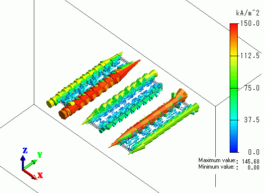
Shown below is the vectors of the current density at Phase=0 [deg].