|
Home / Examples / Magnetic Analysis (Gauss, Static Analysis/Harmonic analysis) / Example 33: Coil-to-Coil Power Transfer
Example 33: Coil-to-Coil Power Transfer
General
-
The power is transfered from the primary coil to the secondary coil.
-
The magnetic field vectors and the electromotive force in the secondary coil are solved.
If you want to solve the transfer power [W], use the electromagnetic analysis [Hertz]. ([Example 28: Coil-to-Coil Power Transfer])
-
Unless specified in the list below, the default conditions will be applied.
-
Obtain this session's project file. (Right-click and choose 'Save link as')
-
Results will vary depending on Femtet version and the PC environment.
Analysis Space
|
Item |
Settings |
|
Analysis Space |
3D |
|
Model Unit |
mm |
Analysis Conditions
|
Item |
Settings |
|
Solver |
Magnetic Analysis [Gauss] |
|
Analysis Type |
Harmonic Analysis |
|
Options |
N/A |
The frequency of the current is set to 30[kHz].
|
Tab |
Setting Item |
Settings |
|
Mesh Tab |
Frequency-Dependent Meshing |
Reference Frequency: 30x103 [Hz] |
|
Harmonic Analysis |
Sweep Type |
Single Frequency |
|
Frequency |
30×103 [Hz] |
Set the Mesh Tab as follows.
|
Tab |
Setting Item |
Setting |
|
Mesh Tab |
Meshing Setup |
Automatically set the general mesh size: Deselect General Mesh Size: 2 [mm] |
Model
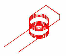
Two coils (Coil1 and Coil2) are placed.
Its inflow/outflow faces if the primary coil (Coil1) are extended to the outside of the air domain. They contact the electric wall of outer boundary condition.
In the magnetic field harmonic analysis, inflow/outflow faces must be outside of the air domain. (for the purpose of calculation with FEM)
In this example, air domain is set to be created automatically. Therefore, the inflow/outflow faces are extended to the outside of air domain.
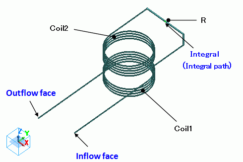
Secondary coil (Coil2) is terminated with R having sufficient resistance value to measure the electromotive force.
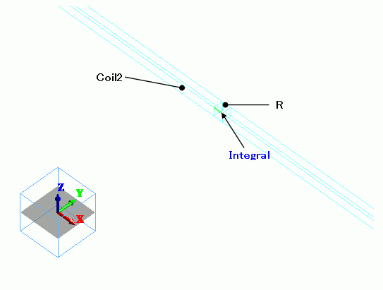
If the boundary condition of integral path is set along the current path, the electromotive force can be calculated by integrating the electric field (current density*resistance) on the integral path.
Basically, the body R is not needed when setting the integral path along the current path of the loop coil. However, the current density is not constant at the cross section of the coil and calculation cannot be done accurately.
By adding the body R having resistance high enough compared to the coil,
the majority of the electric potential difference is generated across the body R, and the current density at the cross section of the body R is almost constant. So the calculation will be accurate.
|
Body Number/Type |
Body Attribute Name |
Material Name |
|
4/Solid |
Coil1 |
008_Cu * |
|
11/Solid |
Coil2 |
008_Cu * |
|
9/Solid |
R |
008_Cu * |
* Available from the material DB
Body attribute of the primary coil is set up as follows to apply the current.
The setting of the secondary coil is not needed as the current is not applied.
|
Body Attribute Name |
Tab |
Settings |
|
Coil1 |
Current |
Waveform: AC Current: 1 [A] Turns: 1 [Turns] Direction: Specify Inflow/Outflow faces Select Inflow Face and Outflow Face. |
The electric conductivity of the body R is set low enough compared to the coil as follows.
|
Material Name |
Tab |
Settings |
|
R |
Conductor Wall |
Conductivity Type: Conductor |
|
Conductivity: 1 [S/m] |
Boundary Conditions
No setting.
Results
To see the electromotive force, go to the [Results] tab
and click [Show Numerical Summary Table]  .
.
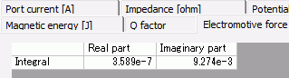
The absolute value is the amplitude of the electromotive force.
About 0.00927 [V] is generated in the secondary coil when 1 [A] is applied in the primary coil.
The electromotive Ve.m. of the secondary coil is expressed as follows.
Ve.m. = jωM I1
As the frequency is 30 kHz, the mutual inductance is 0.491 nH (the results of [Mutual inductance calculation project]), and the amplitude of current I1 at Coil1 is 1 A,
the amplitude |Ve.m| of the electromotive force of the secondary coil is given as 0.00925 V. This matches with the calculated result very well.
-
If you want to solve the transfer power [W], use the electromagnetic analysis [Hertz]. ([Example 28: Coil-to-Coil Power Transfer])
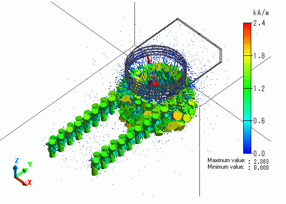
The vectors of the magnetic field are shown below.