


|
Home / Examples / Electromagnetic Analysis [Hertz] / Example 2: Circulator
Example 2: Circulator
General
-
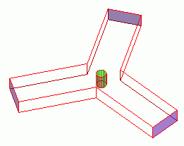
A three-port circulator consisting of a Y-shape waveguide and a ferrite cylinder is analyzed.
-
The device's S-parameters are solved.
-
Unless specified in the list below, the default conditions will be applied.
-
Obtain this session's project file. (Right-click and choose 'Save link as')
-
Results will vary depending on Femtet version and the PC environment.
Analysis Space
|
Item |
Settings |
|
Analysis Space |
3D |
|
Model Unit |
mm |
Analysis Conditions
|
Item |
Settings |
|
Solver |
Electromagnetic Analysis [Hertz] |
|
Analysis Type |
Harmonic Analysis |
|
Options |
Field Data to Save: Don't save |
The harmonic analysis is set up as follows.
|
Tab |
Setting Item |
Settings |
|
Mesh Tab |
Element Type |
2nd-order Element |
|
Adaptive Meshing |
Select [Apply adaptive meshing]. |
|
|
Frequency-Dependent Meshing |
Reference Frequency: 10x109 [Hz] Select [The conductor bodies thicker than the skin depth constitute the boundary condition].
No conductive bodies are used in this example. However the setting above is required. |
|
|
Harmonic analysis |
Sweep Type |
Select Linear Step by Number of Divisions. |
|
Sweep Setting |
Minimum: 0.8x10¹⁰ [Hz] Maximum: 1.2x10¹⁰ [Hz] Division: 20 |
|
|
Sweep Setting |
Select Discrete Sweep |
|
|
Input |
1.0 [W] |
Model
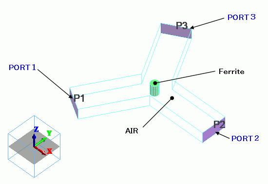
The Y-shape waveguide is created by copying a solid body and uniting them with boolean operation.
The port boundary condition is set on their I/O faces.
The walls of the waveguide are defined as electric wall in the external boundary condition.
Body Attributes and Materials
The mesh size of the ferrite cylinder is set to 1.
|
Body Number/Type |
Body Attribute Name |
Material Name |
Mesh Size |
|
3/Solid |
Air |
000_Air(*) |
1 |
|
4/Solid |
Ferrite |
Ferrite |
|
* Available from the material DB
The static magnetic field applied on the ferrite (Ferrite) is set up in the body attribute.
|
Body Attribute Name |
Tab |
Material Name |
|
Ferrite |
Magnetostatic Field |
1.00X10⁴ [A/m] |
The material properties of Ferrite are set up as follows:
|
Material Name |
Tab |
Properties |
|
Ferrite |
Permittivity |
Relative Permittivity: 11 Dielectric Tangent |
|
Permeability |
Select [Tensor Permeability]. |
|
|
Magnet |
Magnetization Strength: 1.3×10⁻¹
Properties of Ferrite: ΔH: 7.958×10³ [A/m] g Coefficient: 2.0×100 |
Note) The following values are used for the magnet. Saturation magnetic flux density: 1300 [Gauss], Magnetic resonance FWHM: 100 [Oe],
Relative Permittivity 11 Dielectric Tangent 0.0015. 1300[Gauss] = 0.13 [T], 100 [Oe] = 7958 [A/m]
Boundary Conditions
|
Boundary Condition Name/Topology |
Tab |
Boundary Condition Type |
Settings |
|
PORT1/Face |
Electric |
Port |
Reference Impedance: Select
Number of Modes Number of Precalculated Modes: 5 Number of Modes Used in the Actual 3D Analysis: 1 Select Modes: None |
|
PORT2/Face |
Electric |
Port |
Same as PORT1 |
|
PORT3/Face |
Electric |
Port |
Same as PORT1 |
|
Outer Boundary Condition |
Electric |
Electric Wall |
|
The outer boundary of Air:
The outer boundary of Air is set as the electric wall, which is the perfect conductor.
Results
Shown below is the I/O characteristics (S-parameters) between PORT1 and PORT2.
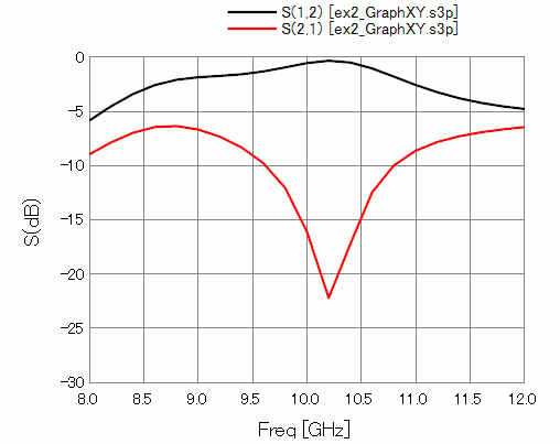
The isolation is exhibited around 10 GHz.