|
Home / Examples / Electromagnetic Analysis [Hertz] / Example 4: Horn Antenna
Example 4: Horn Antenna
General
-
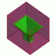
The model is a horn antenna.
-
The S-parameters at the feeding port are solved.
-
Unless specified in the list below, the default conditions will be applied.
-
Obtain this session's project file. (Right-click and choose 'Save link as')
-
Results will vary depending on Femtet version and the PC environment.
Analysis Space
|
Item |
Settings |
|
Analysis Space |
3D |
|
Model Unit |
mm |
Analysis Conditions
|
Item |
Settings |
|
Solver |
Electromagnetic Analysis [Hertz] |
|
Analysis Type |
Harmonic Analysis |
Mesh tab, Harmonic analysis tab and Open boundary tab are set as follows.
|
Tab |
Setting Item |
Settings |
|
Mesh Tab |
Element Type |
2nd-order Element |
|
Adaptive Meshing |
Select [Apply adaptive meshing]. |
|
|
Frequency-Dependent Meshing |
Reference Frequency: 7.1x10¹⁰ [Hz] Select [The conductor bodies thicker than the skin depth constitute the boundary condition].
The surface of Metal is treated as the boundary condition having some loss, as Metal is thicker than the skin depth. See Effect of Mesh Size for reference. |
|
|
Harmonic analysis |
Sweep Type |
Select [Linear Step by Number of Divisions] |
|
Sweep Setting |
Minimum: 7.1x10¹⁰ [Hz] Maximum: 7.1x10¹⁰ [Hz] Division: 0 |
|
|
Sweep Setting |
Select discrete sweep |
|
|
Input |
1.0 [W] |
|
|
Open Boundary |
Type |
Absorbing Boundary |
|
Order of Absorbing Boundary |
1st-order |
Model
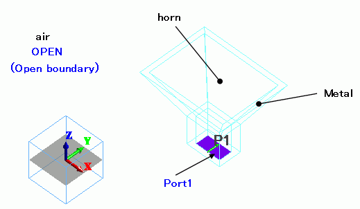
An aluminum horn antenna (Metal) is placed in the cubic air (Air).
The feeding point at the inside of the antenna (horn) is set with the port boundary condition. The open boundary condition is set to the outer surfaces of the cubic air.
Body Attributes and Materials
|
Body Number/Type |
Body Attribute Name |
Material Name |
Mesh Size |
|
50/Solid |
Metal |
001_Al * |
0.3 |
|
51/Solid |
horn |
000_Air(*) |
0.3 |
|
55/Solid |
air |
000_Air(*) |
|
* Available from the material DB
Boundary Conditions
|
Boundary Condition Name/Topology |
Tab |
Boundary Condition Type |
Settings |
|
port1/Face |
Electric |
Port |
Reference Impedance: Select
Number of Modes Number of Precalculated Modes: 5 Number of Modes Used in the Actual 3D Analysis: 1 Select Modes: None |
|
Outer Boundary Condition |
Electric |
Open Boundary |
|
Results
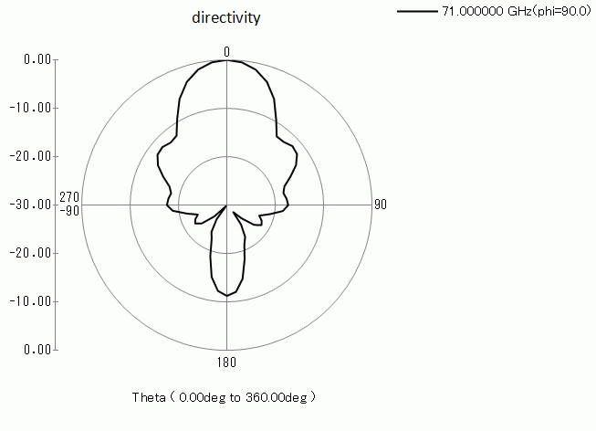
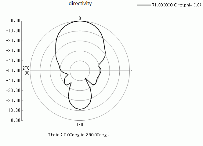
The radiation pattern of the horn antenna is plotted with polar graph.
The unit is [dB].
-
See [[Simple Mode] Electromagnetic Waves Directivity] or [[Detailed Mode] Electromagnetic Waves Directivity] for display of radiation patterns.
Φ=0 [deg], θ=0 to 360 [deg], 60 steps
Φ=90 [deg], θ=0 to 360 [deg], 60 steps