


|
Home / Examples / Electromagnetic Analysis [Hertz] / Example 5: Cavity Resonator
Example 5: Cavity Resonator
General
-
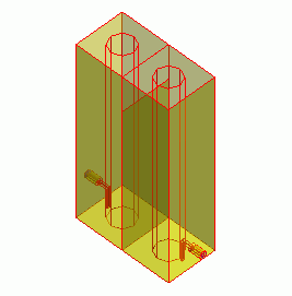
The model is a cavity resonator (1/4 wavelength coaxial).
-
The filtering characteristics of the resonator are solved.
-
Unless specified in the list below, the default conditions will be applied.
-
Obtain this session's project file. (Right-click and choose 'Save link as')
-
Results will vary depending on Femtet version and the PC environment.
Analysis Space
|
Item |
Settings |
|
Analysis Space |
3D |
|
Model Unit |
mm |
Analysis Conditions
|
Item |
Settings |
|
Solver |
Electromagnetic Analysis [Hertz] |
|
Analysis Type |
Harmonic Analysis |
The harmonic analysis is set up as follows.
|
Tab |
Setting Item |
Settings |
|
Mesh Tab |
Element Type |
2nd-order Element |
|
Adaptive Meshing |
Select [Apply adaptive meshing]. |
|
|
Frequency-Dependent Meshing |
Reference Frequency: 1x10⁹ [Hz] Select [The conductor bodies thicker than the skin depth constitute the boundary condition].
The surface of Metal is treated as the boundary condition having some loss, as Metal is thicker than the skin depth. |
|
|
Harmonic analysis |
Sweep Type |
Select [Linear Step by Number of Divisions] |
|
Sweep Setting |
Minimum: 0.95×10⁹ [Hz] Maximum: 1.05x10⁹ [Hz] Division: 40 |
|
|
Sweep Setting |
Select Fast Sweep S-parameter Tolerance: 1×10⁻³ |
|
|
Input |
1.0 [W] |
Model
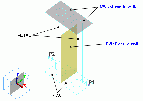
The model consists of 2 cavity resonators with one end open. The resonators are coupled through the coupling window and also with the magnetic loop externally.
It is a 2-stage filter.
The whole model
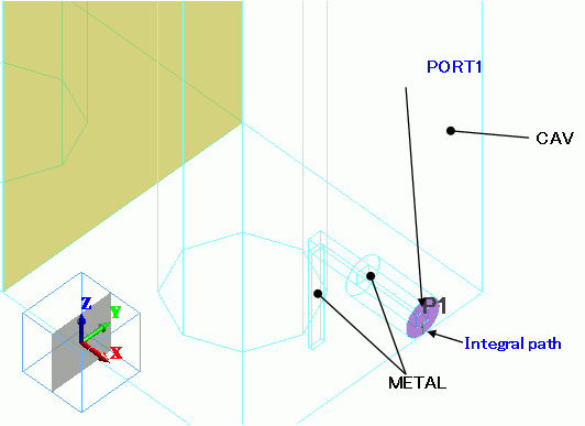
The detail around port
Body Attributes and Materials
The boolean operation is not performed for CAV and METAL,
even though they are overlapping. The boolean will be done automatically during meshing.
Body #4 is an imprinting body and located at the coupling window.
The electric wall boundary condition is set to the body. Wire bodies are created at the ports.
The integral path boundary condition is set on the wire body.
|
Body Number/Type |
Body Attribute Name |
Material Name |
|
0/Solid |
CAV |
000_Air(*) |
|
1/Solid |
METAL |
008_Cu * |
|
2/Solid |
METAL |
008_Cu * |
|
3/Solid |
CAV |
000_Air(*) |
|
4/Sheet |
Imprinting body |
|
|
5/Solid |
METAL |
008_Cu * |
|
6/Solid |
METAL |
008_Cu * |
|
8/Solid |
CAV |
000_Air(*) |
|
9/Solid |
METAL |
008_Cu * |
|
10/Solid |
METAL |
008_Cu * |
|
11/Solid |
METAL |
008_Cu * |
|
14/Solid |
METAL |
008_Cu * |
|
15/Solid |
CAV |
000_Air(*) |
* Available from the material DB
Boundary Conditions
The port boundary conditions (PORT1, PORT2) are set on the ports of the filter.
The integral path is required between the hot and the ground for two-conductor ports.
The integral path is used to calculate the characteristic impedance of the port.
S-parameters can be converted based on the characteristic impedance.
|
Boundary Condition Name/Topology |
Tab |
Boundary Condition Type |
Settings |
|
PORT1/Face |
Electric |
Port |
Reference Impedance: Number of Modes Number of Precalculated Modes: 5 Number of Modes Used in the Actual 3D Analysis: 1 Select Modes: None |
|
PORT2/Face |
Electric |
Port |
Same as PORT1 |
|
EW/Face |
Electric |
Electric Wall |
|
|
MW/Face |
Electric |
Magnetic Wall |
|
|
Outer Boundary Condition |
Electric |
Electric Wall |
|
The outer boundary of air:
The boundary between air and Metal is the lossy conductor surface of the material of Matal.
The outer boundary of Air, which does not have any boundary conditions and is adjoining with the exterior, is set with
the electric wall, representing a perfect conductor.
Results
The S-parameters plots are shown below.
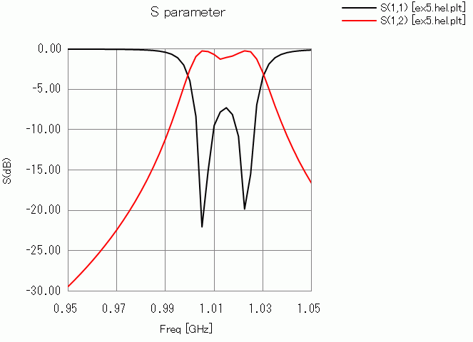
The pass band is around 1.01 [GHz].