|
Home / Examples / Electromagnetic Analysis [Hertz] / Example 10: Coil Formed in a Substrate
Example 10: Coil Formed in a Substrate
General
-
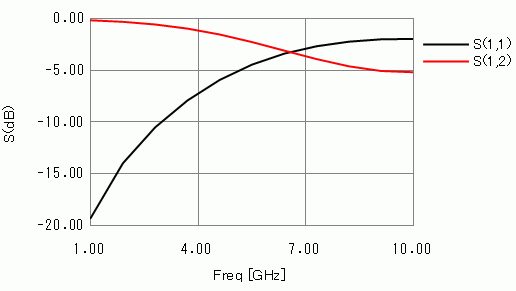
The frequency response of a coil formed in a substrate is solved.
-
Unless specified in the list below, the default conditions will be applied.
-
Obtain this session's project file. (Right-click and choose 'Save link as')
-
Results will vary depending on Femtet version and the PC environment.
Analysis Space
|
Item |
Settings |
|
Analysis Space |
3D |
|
Model Unit |
mm |
Analysis Conditions
|
Item |
Settings |
|
Solver |
Electromagnetic Analysis [Hertz] |
|
Analysis Type |
Harmonic Analysis |
Harmonic Analysis tab and Open Boundary tab are set as follows.
|
Tab |
Setting Item |
Settings |
|
Mesh Tab |
Element Type |
2nd-order Element |
|
Adaptive Meshing |
Select [Apply the adaptive meshing]. |
|
|
Frequency-Dependent Meshing |
Reference frequency: 5x10⁹ [Hz] Select [The conductor bodies thicker than the skin depth constitute the boundary condition].
The surface of Metal is treated as the boundary condition having some loss, as Metal is thicker than the skin depth. |
|
|
Harmonic analysis |
Sweep Type |
Select [Linear Step by Number of Divisions] |
|
Sweep Setting |
Minimum: 1×10⁹ [Hz] Maximum: 10x109 [Hz] Division Number: 10 |
|
|
Sweep Setting |
Select Fast Sweep S-Parameter Tolerance: 1x10⁻³ |
|
|
Input |
1.0 [W] |
|
|
Open Boundary |
Type |
Absorbing Boundary |
|
Order of Absorbing Boundary |
1st-order |
Model
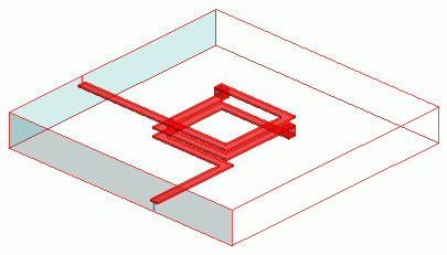
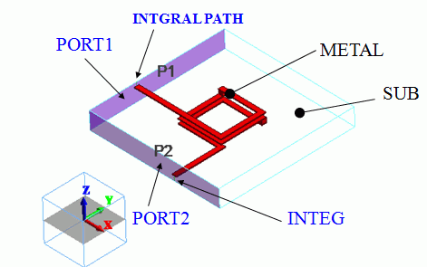
A coil (METAL) of a solid body is created inside a substrate (SUB). The ports (PORT1,PORT2) are set on the substrate faces where coil leads come out. Other substrate faces are set with the outer boundary condition to [Electric Wall].
Body Attributes and Materials
|
Body Number/Type |
Body Attribute Name |
Material Name |
|
0/Solid |
SUB |
006_Glass_epoxy * |
|
4/Solid |
METAL |
003_Ag * |
|
8/Solid |
METAL |
003_Ag * |
|
14/Solid |
METAL |
003_Ag * |
|
15/Solid |
METAL |
003_Ag * |
|
16/Solid |
METAL |
003_Ag * |
* Available from the material DB
Boundary Conditions
|
Boundary Condition Name/Topology |
Tab |
Boundary Condition Type |
Settings |
|
PORT1/Face |
Electric |
Port |
Reference Impedance: Select [Specify] and enter 50 ohms. Number of Modes Number of Precalculated Modes: 5 Number of Modes Used in the Actual 3D Analysis: 1 Select Modes: None |
|
PORT2/Face |
Electric |
Port |
Same as Above. |
|
Outer Boundary Condition |
Electric |
Electric Wall |
N/A |
Results
The frequency response of S11 and S22 is shown below.