


|
Home / Examples / Electromagnetic Analysis [Hertz] / Example 13: Corrugated Waveguide
Example 13: Corrugated Waveguide
General
-
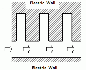
The dispersion curve of a corrugated waveguide are solved. The model has uniform structure in the depth direction.
-
The periodic boundary condition is applied in the 3D resonant analysis.
-
Unless specified in the list below, the default conditions will be applied.
-
Obtain this session's project file. (Right-click and choose 'Save link as')
-
Results will vary depending on Femtet version and the PC environment.
Analysis Space
|
Item |
Settings |
|
Analysis Space |
3D |
|
Model Unit |
mm |
Analysis Conditions
|
Item |
Settings |
|
Solver |
Electromagnetic Analysis [Hertz] |
|
Analysis Type |
Resonant Analysis |
Mesh tab, Harmonic analysis tab and Open boundary tab are set as follows.
|
Tab |
Setting Item |
Settings |
|
Mesh Tab |
Element Type |
2nd-order Element |
|
Resonant Analysis |
Number of Modes |
5 |
|
Approximated Frequency |
0 [Hz] |
|
|
Input Power |
1.0 [W] |
Model
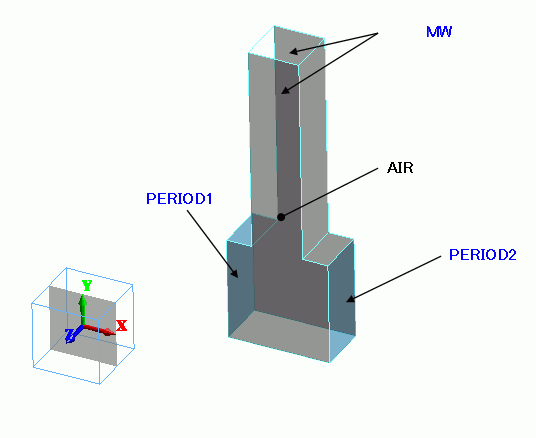
The air domain is defined with a solid body. No boundary condition is set on the faces normal to Z axis.
The waveguide has a periodic structure. Cut out one unit to set the periodic boundary condition [PERIOD1] and [PERIOD2] to its cross sections.
The other faces are set with Electric wall PEC.
Body Attributes and Materials
|
Body Number/Type |
Body Attribute Name |
Material Name |
|
4/Solid |
AIR |
000_Air(*) |
* Available from the material DB
Boundary Conditions
|
Boundary Condition Name/Topology |
Tab |
Boundary Condition Type |
Settings |
|
MW/Face |
Electric |
Magnetic Wall |
N/A |
|
PERIOD1/Face |
Symmetry/Continuity |
Periodic |
N/A |
|
PERIOD2/Face |
Symmetry/Continuity |
Periodic |
N/A |
|
Outer Boundary Condition |
Electric |
Electric Wall |
N/A |
Boundary Pair
|
Boundary Condition Name/Topology |
Boundary Condition Name/Topology |
Boundary Condition Type |
Settings |
|
PERIOD1/Face |
PERIOD2/Face |
Translational |
1 ≤ θ ≤ 359 |
Results
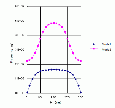
The phase difference of periodic boundary is varied in the range of 1 ≤ θ ≤ 359. The resonant frequencies are plotted for each angle.
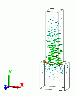
The electric field at θ=180.
This is the lowest - frequency resonant mode.
[Reference]
[1] Yu Zbu and Andreas Cangellaris, "Multigrid Finite Element Methods for Electromagnetic Field Modeling", The IEEE Press Series on Electromagnetic Wave Theory, pp. 396-397.