


|
Home / Examples / Electromagnetic Analysis [Hertz] / Example 3: Antenna with Impedance-Matching Components
Example 3: Antenna with Impedance-Matching Components
General
-
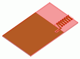
The characteristics of a spiral antenna connected to impedance-matching components are analyzed.
-
The impedance characteristics and radiation patterns are obtained.
-
Unless specified in the list below, the default conditions will be applied.
-
Obtain this session's project file. (Right-click and choose 'Save link as')
-
Results will vary depending on Femtet version and the PC environment.
Analysis Space
|
Item |
Settings |
|
Analysis Space |
3D |
|
Model unit |
mm |
Analysis Conditions
|
Item |
Settings |
|
Solver |
Electromagnetic Analysis [Hertz] |
|
Analysis Type |
Harmonic Analysis |
Mesh tab, Harmonic analysis tab and Open boundary tab are set as follows.
|
Tab |
Setting Item |
Settings |
|
Mesh Tab |
Element type |
2nd-order Element |
|
Adaptive Meshing |
Select [Apply adaptive meshing]. |
|
|
Frequency-Dependent Meshing |
Reference frequency: 1.5x10⁹ [Hz] Select [The conductor bodies thicker than the skin depth constitute the boundary condition]. |
|
|
Harmonic analysis |
Sweep Type |
Select [Linear Step by Number of Divisions] |
|
Sweep Setting |
Minimum: 1×10⁹ [Hz] Maximum: 2x10⁹ [Hz] Division: 100 |
|
|
Sweep Setting |
Select Fast sweep S-parameter Tolerance: 1x10⁻³ |
|
|
Input |
1.0 [W] |
|
|
Open boundary |
Type |
Absorbing Boundary |
|
Order of Absorbing Boundary |
1st-order |
Model
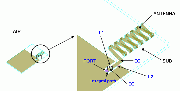
The spiral antenna is formed with a conductive strip wound around the alumina (ANTENNA) . It is mounted on a substrate (SUB) made of glass epoxy.
Two inductors are inserted as impedance-matching components near the feeding point. The air (AIR) encloses the substrate and the antenna entirely.
The open boundary condition is set on the surface of "AIR".
The electrode is set with [Surface Impedance] boundary condition (EC). Inductors are set with [Lumped Constant] boundary condition.
Body Attributes and Materials
|
Body Number/Type |
Body Attribute Name |
Material Name |
|
0/Solid |
ANTENNA |
001_Alumina * |
|
1/Solid |
SUB |
006_Glass_epoxy * |
|
9/Solid |
AIR |
000_Air(*) |
* Available from the material DB
Boundary Conditions
|
Boundary Condition Name/Topology |
Tab |
Boundary Condition Type |
Settings |
|
PORT/Face |
Electric |
Port |
Reference Impedance: Select Specify Number of Modes Number of Precalculated Modes: 5 Number of Modes Used in the Actual 3D Analysis: 1 Select modes: None |
|
L1/Face |
Electric |
Lumped Constant |
2.0X10⁻⁹ [H] |
|
L2/Face |
Electric |
Lumped Constant |
4.0X10⁻⁹ [H] |
|
EC |
Electric |
Surface Impedance |
Conductivity: 1.0x10⁷ [S/m] |
|
Outer Boundary Condition |
Electric |
Open Boundary |
Results
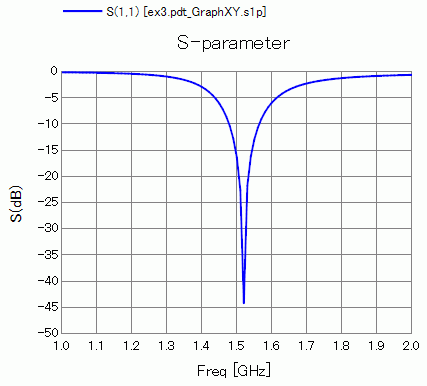
S-parameter S11 at the feeding point is shown below.
It is matched at about 1.5 GHz.
-
How to Display Graph
On the [Results] tab, go to
  and click ▼ at the right side of [Show Characteristics Chart]. Click [S/Y Parameters] on the submenu.
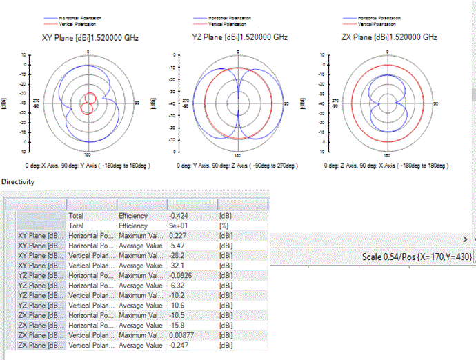
The radiation pattern and efficiency of the antenna at 1.52 [GHz] are shown below.
-
How to Display
On the [Results] tab, go to and click ▼ at the side of [Show Characteristics Chart]. Click [Directivity Graph] on the submenu. -
See [[Simple Mode] Electromagnetic Waves Directivity] for more information.
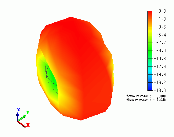
The radiation pattern in 3D is shown below.
-
How to Display
On the [Results] tab, go to and click ▼ at the side of [Show Characteristics Chart]. Click [Directivity in 3D] on the submenu. -
See [3D Electromagnetic Waves Directivity] for more information.